Liquid discharge apparatus

Active Publication Date: 2022-03-08
BROTHER KOGYO KK
View PDF10 Cites 0 Cited by
  • Summary
  • Abstract
  • Description
  • Claims
  • Application Information

AI Technical Summary

Benefits of technology

[0028]in a second period after the first period, drive the second pump with the driving of the first pump being continued, such that an average power consumption of the second pump in the second period is lower than an average power consumption of the second pump in the first period.
[0029]In the present disclosure, when liquid circulation is performed, and when the sto

Problems solved by technology

In this configuration, when a return-side channel, through which ink recovered from the ink-jet head flows, has a high channel resistance or a high internal pressure, positive pressure is applied to meniscuses for

Method used


Image

  • Liquid discharge apparatus
  • Liquid discharge apparatus
  • Liquid discharge apparatus

Examples


Example

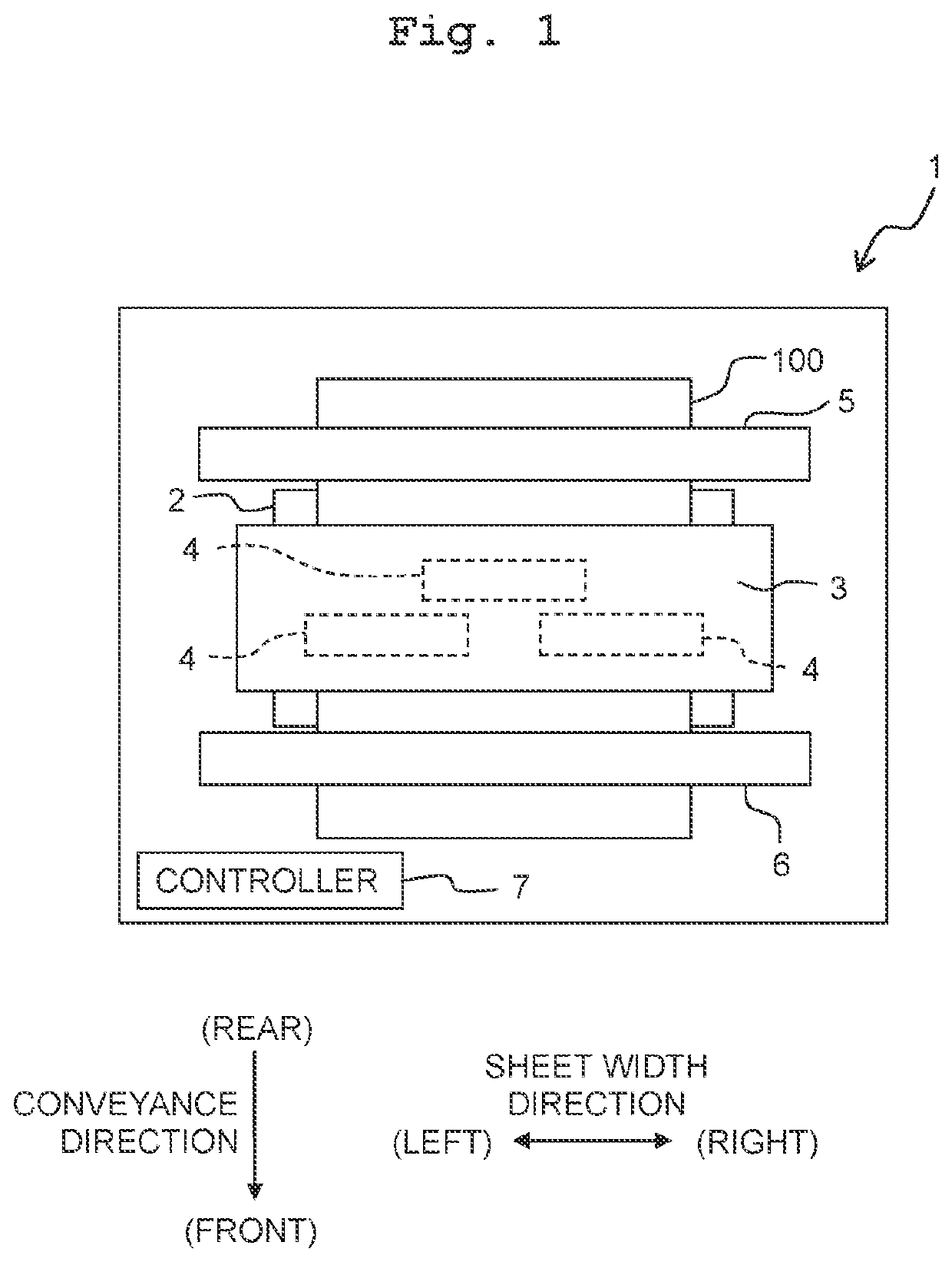
[0039]Referring to FIGS. 1 to 3, the first embodiment of the present disclosure is described below. A sheet width direction indicated in FIG. 1 is defined as a left-right direction of a printer 1. The right side of FIG. 1 is the right side of the printer 1, and the left side of FIG. 1 is the left side of the printer 1. An upstream side in a conveyance direction of FIG. 1 is defined as a rear side of the printer 1, and a downstream side in the conveyance direction of FIG. 1 is defined as a front side of the printer 1. A direction orthogonal to the sheet width direction and the conveyance direction (a direction orthogonal to a sheet surface of FIG. 1) is defined as an up-down direction of the printer 1. A fore side (front side) of the sheet surface of FIG. 1 is defined as up (upward) of the primer 1, and a far side (the other side) of the sheet surface of FIG. 1 is defined as down (downward) of the printer 1.

[0040]

[0041]As depicted in FIG. 1, the printer 1 (“the liquid discharging app...

Example

Second Embodiment

[0090]The second embodiment of the present disclosure is explained below. The constitutive parts or components, which are the same as or equivalent to those of the first embodiment, are designated by the same reference numerals, any explanation therefor is omitted as appropriate.

[0091]As depicted in FIG. 7, a printer 101 according to the second embodiment includes an atmosphere open channel 134 through which the subtank 3 communicates with air or the atmosphere, and an atmosphere open valve 138 (a “valve” of the present disclosure) that opens or closes the atmosphere open channel 134.

[0092]An ink-jet head 104 according to the second embodiment includes nozzles 120 arranged in the sheet width direction, the first manifold 131 that communicates with part of the nozzles 120, and the second manifold 132 that communicates with remaining nozzles 120. The first manifold 131 and the second manifold 132 extend in the sheet width direction. The first end of the first manifold...


PUM


Abstract

A liquid discharge apparatus includes: a liquid discharge head having a nozzle; a storage chamber that stores liquid; a supply channel communicating with the liquid discharge head and an outlet of the storage chamber; a return channel communicating with the liquid discharge head and an inlet of the storage chamber; a first pump that is provided in the supply channel and feeds the liquid stored in the storage chamber to the liquid discharge head; a gas channel connected to the storage chamber; a second pump that is connected to the storage chamber via the gas channel and discharges gas from inside the storage chamber; and a controller. The controller continues driving of the first pump and driving of the second pump in a first period, and stops the driving of the second pump with the driving of the first pump being continued, in a second period after the first period.

Description

CROSS REFERENCE TO RELATED APPLICATION[0001]The present application claims priority from Japanese Patent Application No. 2019-226312 filed on Dec. 16, 2019, the disclosure of which is incorporated herein by reference in its entirety.BACKGROUNDField of the Invention[0002]The present disclosure relates to a liquid discharge apparatus that discharges liquid from nozzles.Description of the Related Art[0003]There is known a liquid discharge apparatus that circulates liquid in the vicinity of nozzles. Circulating the liquid in the vicinity of nozzles can discharge air bubbles entering the vicinity of nozzles, and inhibits the increase in viscosity of liquid in the vicinity of nozzles.[0004]There is also known a liquid discharge apparatus that circulates ink in a manifold of an ink-jet head. Circulating the ink in the manifold keeps temperature of ink in the ink-jet head fixed, and disperses components of ink settled in the manifold.SUMMARY[0005]A pump may be disposed in a supply-side chan...

Claims


Application Information

Patent Timeline
IPC IPC(8): B41J2/175B41J2/145B41J2/18B41J2/14
CPCB41J2/17596B41J2/145B41J2/18B41J2002/14354B41J2/19B41J2/175B41J29/38
Inventor TANABE, YUMA
Owner BROTHER KOGYO KK
Why Eureka
Try Eureka