Switching status determination device and method for determining switching status

Active Publication Date: 2006-10-17
DENSO CORP
View PDF15 Cites 4 Cited by
  • Summary
  • Abstract
  • Description
  • Claims
  • Application Information

AI Technical Summary

Benefits of technology

[0008]A voltage adjustment circuit is provided to adjust the DC voltage to at least two levels: high or low. For instance, the DC voltage is set to a constant level and periodically adjusted to a high level. By setting the voltage, which is periodically applied to the contacts, to a low level, the power consumption for the determination is lowered. Furthermor

Problems solved by technology

Furthermore, a large amount of current is passed by

Method used


Image

  • Switching status determination device and method for determining switching status
  • Switching status determination device and method for determining switching status
  • Switching status determination device and method for determining switching status

Examples


Example

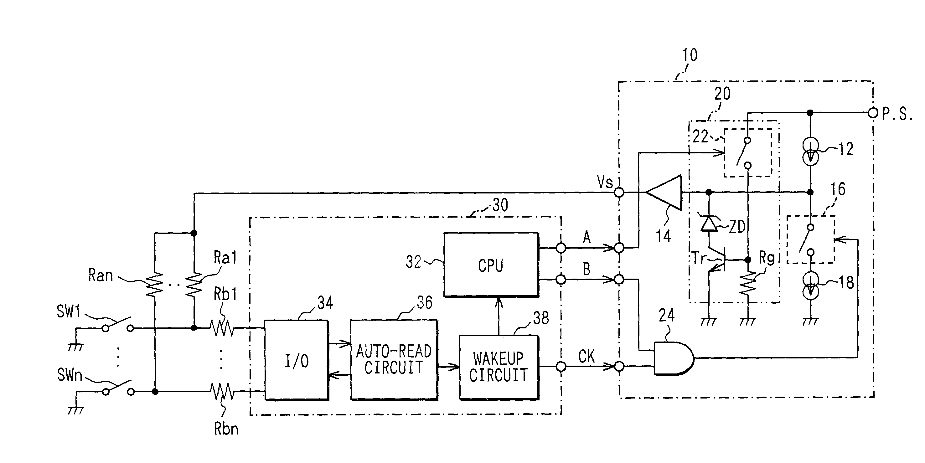
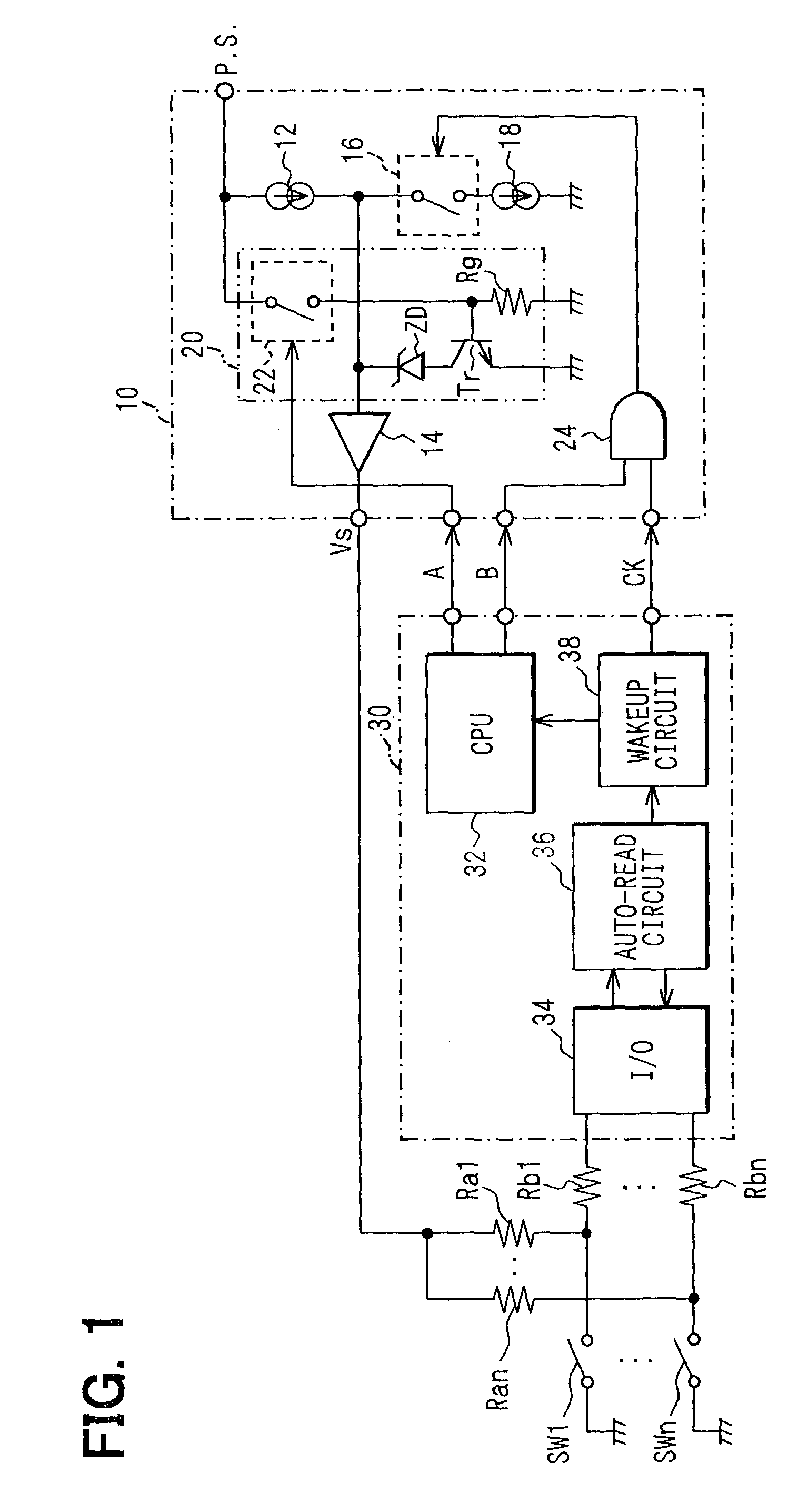
[0012]The preferred embodiments of the present invention will be explained with reference to the accompanying drawings. Referring to FIG. 1, the switching status determination device includes a custom IC 10 and a microcomputer 30. The device determines status of each switch SW1–SWn used for manual operations of electronic devices, such as door locks and power windows, installed in a vehicle. The custom IC 10 applies a DC voltage (a sampling voltage) between contacts of each switch SW1–SWn via a respective resistor Ra1-Ran to determine the status of the switch SW1–SWn.

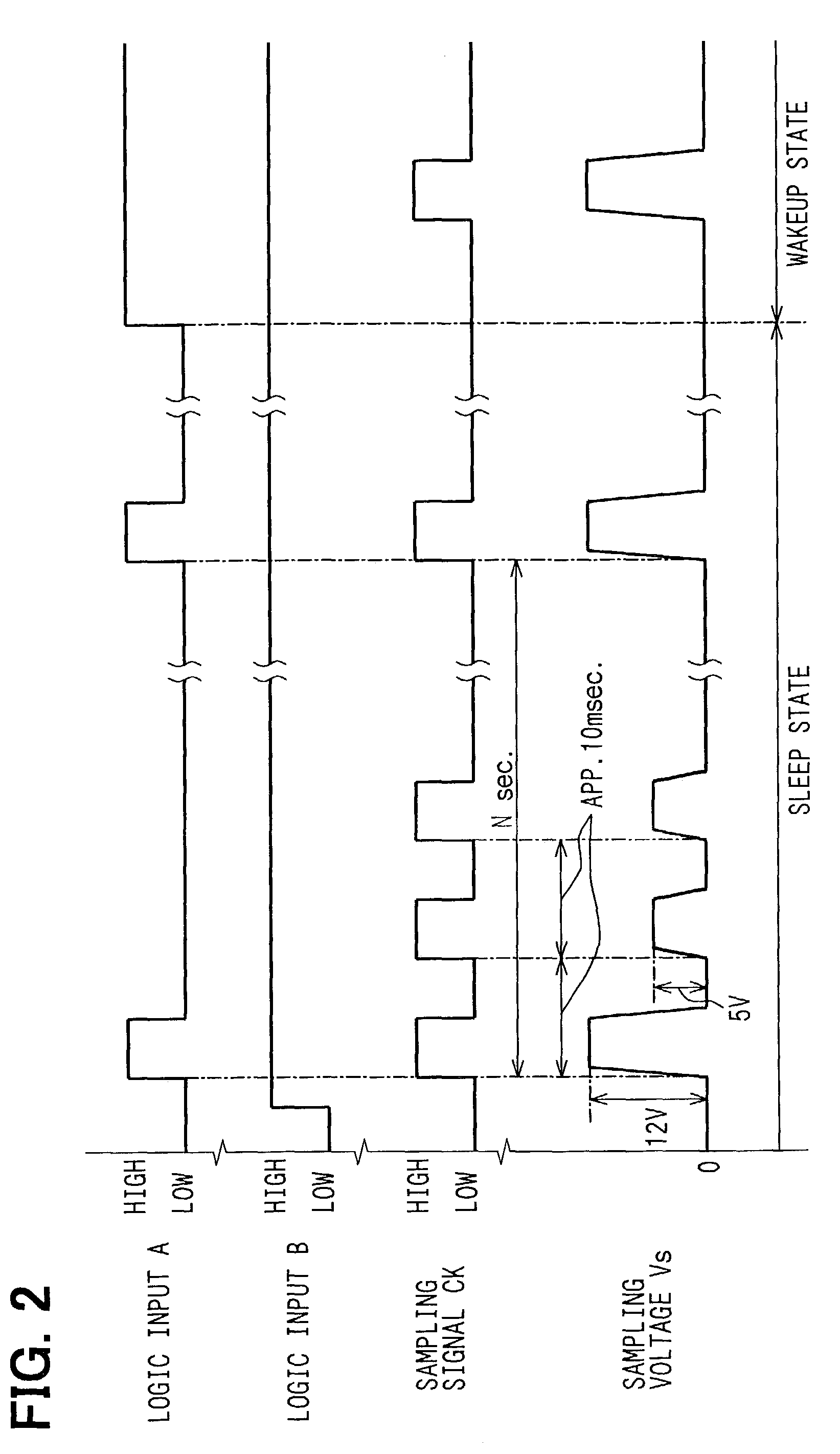
[0013]The microcomputer 30 controls timing of a sampling voltage application to the contacts. It determines the status of the switch SW1–SWn based on whether a current is passed between the contacts by the sampling voltage application. The microcomputer 30 controls devices, which manually operated via the switch SW1–SWn, based on the determination result. The manually operated devices include a door lock actuator and a ...


PUM


Abstract

A sampling voltage is periodically applied between contacts of a switch of a device to determine a status of the switch. When a CPU is in a sleep state and the status of the switch is determined closed, the CPU is activated. The sampling voltage when the CPU is in the sleep state is adjusted lower than the one when the CPU is in the wakeup state. This reduces power consumption for the switch status determination. The sampling voltage adjusted at the lower level periodically adjusted to a higher level to reduce errors in the determination due to insulation films on the contacts.

Description

CROSS REFERENCE TO RELATED APPLICATION[0001]This application is based on and incorporates herein by reference Japanese Patent Application No. 2002-164339 filed on Jun. 5, 2002.FIELD OF THE INVENTION[0002]The present invention relates to a switching status determination device and a method for determining a switching status.BACKGROUND OF THE INVENTION[0003]A switching status determination device is used in a control device that controls other devices in a vehicle based on a status of manual switches. The device determines the status of the manual switches, whether they are open or closed. One of such devices is disclosed in JP-B2-4-44065. In this device, a voltage is periodically applied between contacts of a switch. Then, it is determined whether current flows between the contacts while the voltage is applied. The status of the switch is determined based on the current flowing condition.[0004]In recent years, more and more electronic devices are installed in a vehicle, and a total a...

Claims


Application Information

Patent Timeline
IPC IPC(8): G01R31/02H01H9/00G05B9/02H01H9/16
CPCG05B9/02H01H9/167
Inventor NAKAZAWA, ATSUSHITAKAGI, NOBUTOMO
Owner DENSO CORP
Why Eureka
Try Eureka