

Top cover for axial rotary combine having coned transition
- Summary
- Abstract
- Description
- Claims
- Application Information
AI Technical Summary
Benefits of technology
Problems solved by technology
Method used
Image

Examples
Embodiment Construction
[0034]While this invention is susceptible of embodiment in many different forms, there are shown in the drawings, and will be described herein in detail, specific embodiments thereof with the understanding that the present disclosure is to be considered as an exemplification of the principles of the invention and is not intended to limit the invention to the specific embodiments illustrated.
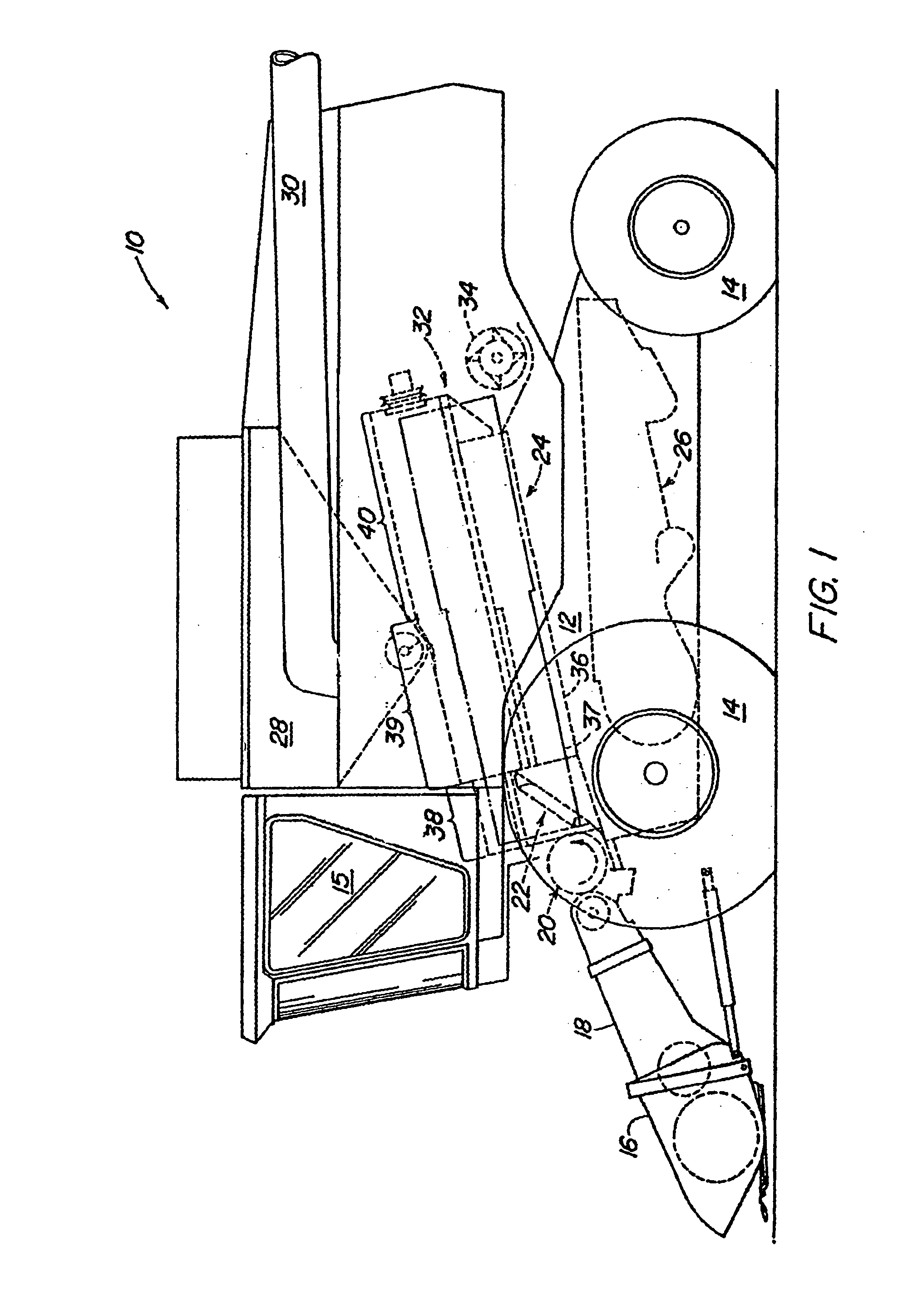
[0035]FIG. 1 shows an agricultural combine 10 comprising a supporting structure 12 having ground engaging wheels 14 extending from the supporting structure. The operation of the combine is controlled from operator's cab 15. A harvesting platform 16 is used for harvesting a crop and directing it to a feederhouse 18. The harvested crop is directed by the feederhouse 18 to a beater 20. The beater directs the crop upwardly through an inlet transition section 22 to the axial crop processing unit 24.
[0036]The crop processing unit 24 threshes and separates the harvested crop material. Grain and chaff fa...
PUM
 Abstract
Description
Claims
Application Information