Abnormality diagnostic method and abnormality diagnostic device for feed axis device

a technology of abnormality and diagnostic method, which is applied in the direction of structural/machine measurement, instruments, manufacturing tools, etc., can solve the problems of abnormal noise, shape defect, accuracy failure, etc., and achieve the effect of increasing the risk of failure, low cost and low risk

Active Publication Date: 2022-03-08
OKUMA CORP
View PDF3 Cites 0 Cited by
  • Summary
  • Abstract
  • Description
  • Claims
  • Application Information

AI Technical Summary

Benefits of technology

[0013]With the disclosure, the abnormality diagnosis can be performed without adding another component such as a sensor to the minimum configuration used for the control of the feed axis device. As a result, the increase of a failure risk due to the addition of, for example, the sensor do not occur. Therefore, the abnormality diagnosis for the feed axis device can be performed at low cost and low risk.

Problems solved by technology

However, in a machine that has been operated for several years, a preload loss by abrasion and a damage due to an entrance of foreign matter, a lubrication failure, or the like cause an accuracy failure, an abnormal noise, and the like possibly to occur.
In the above-described state, a trouble of a shape defect, a failure in a pick feed direction, and the like of a workpiece occurs.
However, since the machine in JP-A-2007-219689 employs a full-closed loop method, it cannot be applied to a machine that employs the semi-closed loop method.
In the methods, since there are more components than those in the minimum configuration used for controlling the feed axis device, there is a problem of causing a cost increase, and the increased parts that possibly break down causes a problem of an increased failure risk.
As a result, the increase of a failure risk due to the addition of, for example, the sensor do not occur.

Method used


Image

  • Abnormality diagnostic method and abnormality diagnostic device for feed axis device
  • Abnormality diagnostic method and abnormality diagnostic device for feed axis device
  • Abnormality diagnostic method and abnormality diagnostic device for feed axis device

Examples


Embodiment Construction

[0018]The following describes embodiments of the disclosure based on the drawings.

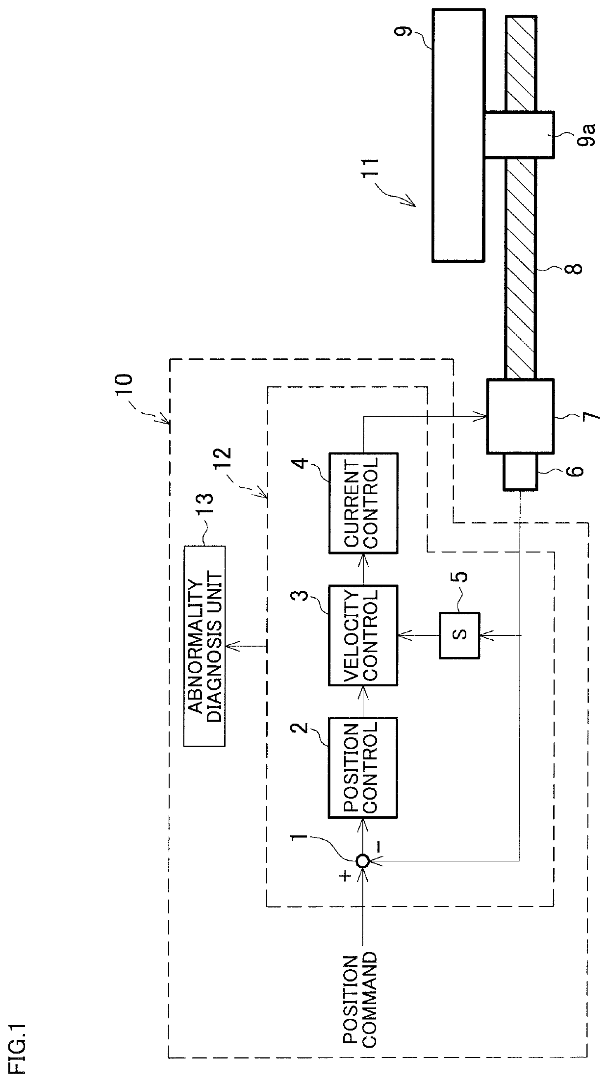
[0019]FIG. 1 is an exemplary block diagram of a feed axis device and a position control device in a machine tool to which the disclosure is applied.

[0020]A feed axis device 11 rotatably drives a ball screw 8 with a motor 7 to linearly move a moving body 9 on which a nut 9a is screwed with the ball screw 8.

[0021]In a position control device 12, a position command from an NC device 10 and a current position from a position detector 6 mounted on the motor 7 are input to an adder 1, and then, a calculated position deviation is input to a position controller 2. The position controller 2 generates a speed command value corresponding to a position error amount. A velocity controller 3 generates a torque command value corresponding to a speed detection value obtained by operating the speed command value and the current position with a differentiator 5. A current controller 4 controls a current to the motor 7 b...


PUM


Abstract

An abnormality diagnostic method for a feed axis device that diagnoses an abnormality of the feed axis device including a screw shaft and a nut, the feed axis device being incorporated in mechanical equipment, the abnormality diagnostic method includes controlling an operation of the feed axis device such that the screw shaft operates in a predetermined operating pattern, detecting a physical quantity signal generated from the feed axis device, and performing an abnormality diagnosis for the feed axis device based on the physical quantity signal detected by the detecting in accordance with a predetermined abnormality diagnosis algorithm. The performing includes performing a frequency analysis on the physical quantity signal to extract respective frequencies corresponding to a plurality of operating positions in the operating pattern and performing the abnormality diagnosis based on change of the frequencies corresponding to the respective operating positions.

Description

[0001]This application claims the benefit of Japanese Patent Application Number 2019-202550 filed on Nov. 7, 2019, the entirety of which is incorporated by reference.BACKGROUND1. Technical Field[0002]The disclosure relates to a method and a device that diagnose an abnormality of a feed axis device, in mechanical equipment such as a machine tool including the feed axis device by a ball screw.2. Related Art[0003]For example, among feed axis devices of machine tools, a system that transmits rotational motion of a motor to a ball screw to drive the ball screw is often used. However, in a machine that has been operated for several years, a preload loss by abrasion and a damage due to an entrance of foreign matter, a lubrication failure, or the like cause an accuracy failure, an abnormal noise, and the like possibly to occur. In the above-described state, a trouble of a shape defect, a failure in a pick feed direction, and the like of a workpiece occurs. Accordingly, it is preferred that ...

Claims


Application Information

Patent Timeline
Patent Type & Authority Patents(United States)
IPC IPC(8): G06F11/30G01M99/00
CPCG01M99/005B23Q17/12G01M7/00G01M13/028
Inventor ITO, MARIKOHONGO, TAKUMI
Owner OKUMA CORP
Why Eureka
Try Eureka