Method for manufacturing inkjet printable paper or foil for use as a decor paper or foil

a printing paper or foil and decor paper technology, applied in the field of panels, can solve the problems of pigments quickly precipitating from the ink mixture, and achieve the effects of excellent print definition, and reduced risk of failing nozzles

Active Publication Date: 2021-10-19
FLOORING IND LTD
View PDF23 Cites 1 Cited by
  • Summary
  • Abstract
  • Description
  • Claims
  • Application Information

AI Technical Summary

Benefits of technology

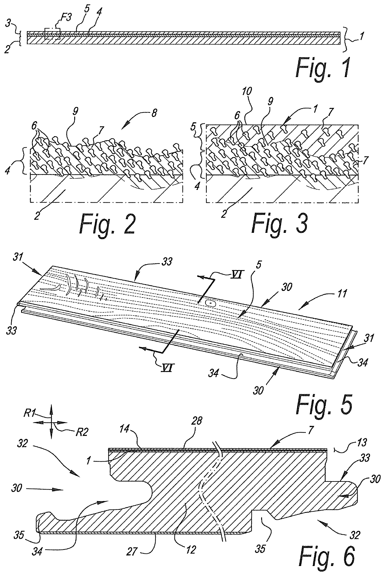
[0017]Pigments of inkjet inks are stabilized to attain a good dispersion in the ink vehicle and to avoid coagulation of the pigments, in particular to avoid clogging of the nozzles in the inkjet heads. This stabilization is in inkjet inks obtained by means of electrosteric effect between the pigments. The ink reactive compound preferably is a substance that breaks up the stabilization of the pigments in the jetted droplets, or in other word an ink destabilizing agent. The inventors have found that the addition of such an ink reactive compound to an inkjet receiver coating based on a pigment and binder mixture tremendously enhances the obtainable printing quality, more particularly the attainable color density, of a print on a paper layer or foil. The ink reactive compound captures the ink, more particularly the pigments, upon the first interaction with it. By interfering or breaking up the electrosteric functions on the pigments, such that the pigments quickly precipitate from the ink mixture and are only minimally driven deeper into the coating together with the inks vehicle. This immediate immobilization of the pigment leads to a superior color density of the print. The pigment and binder system of the ink receiver coating absorbs the vehicle of the ink, thereby also preventing bleeding, particularly while printing on paper, or smearing of the ink, particularly while printing on foils, which also in itself may lead to an enhanced printing quality.
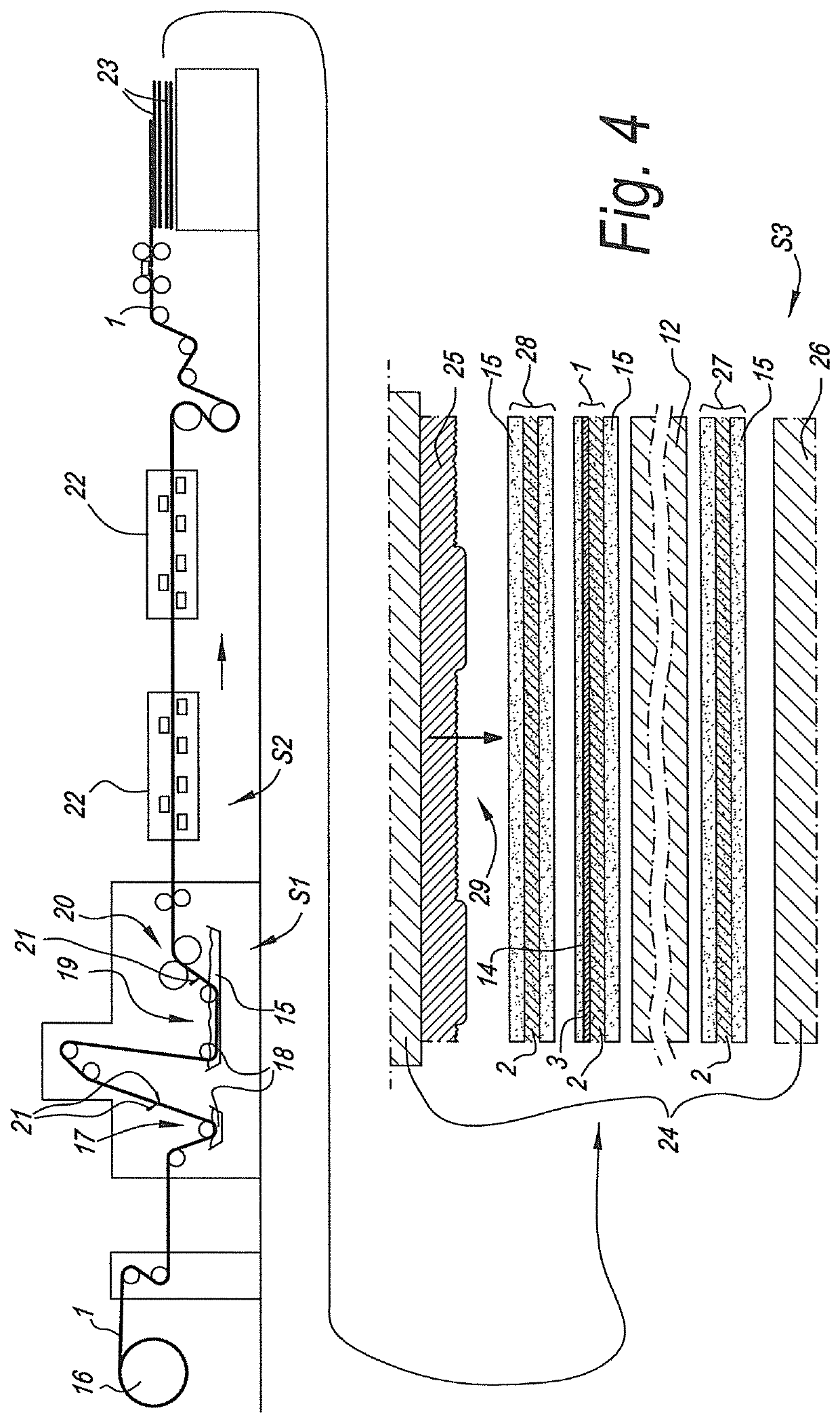
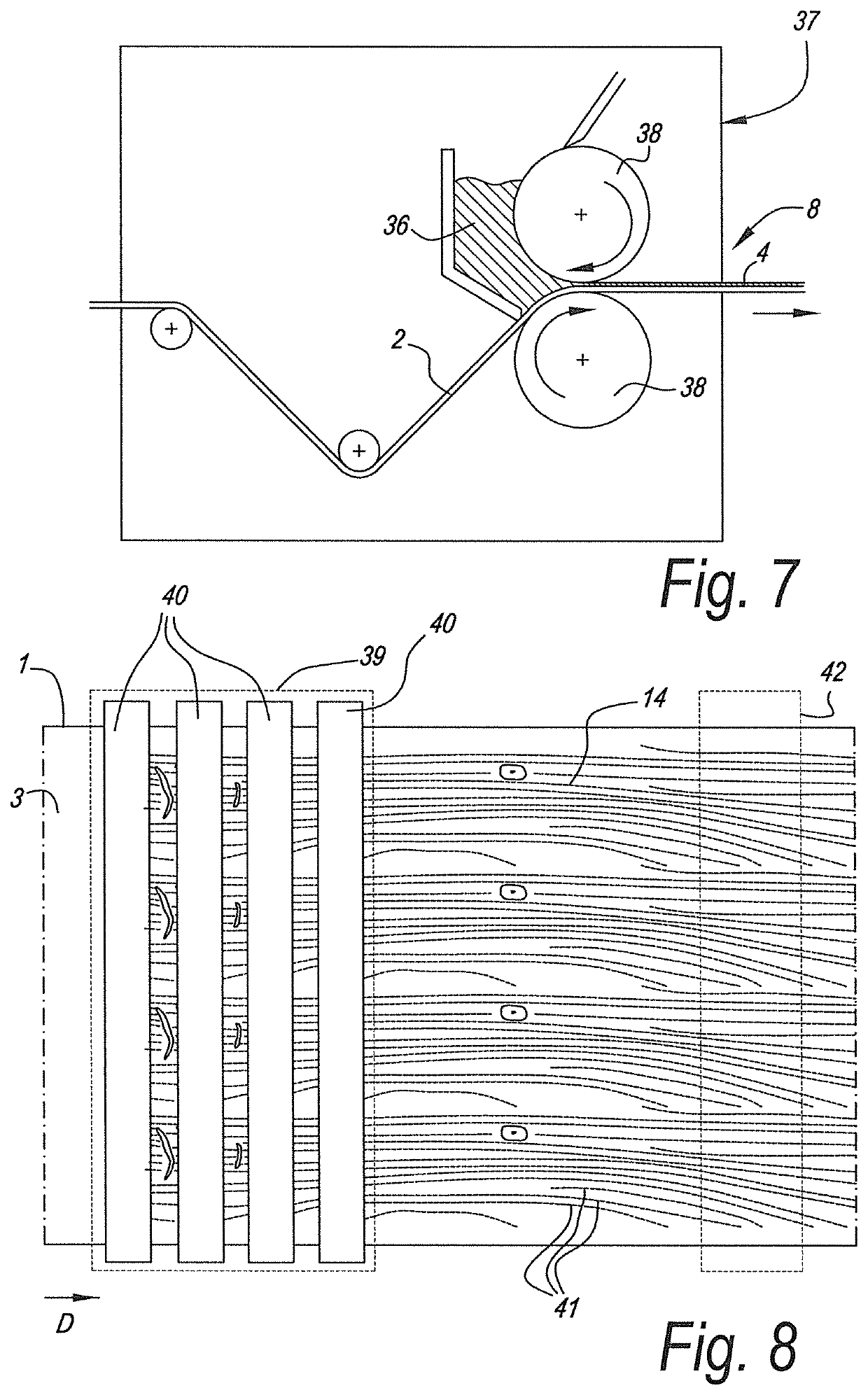
[0109]Preferably said digital inkjet printer is of the single pass type, wherein the paper layer or foil is provided with said printed pattern in a single continuous relative movement of the paper layer with respect to the printer or print heads. It is not excluded that other digital inkjet printers are used to put the invention into practice, such as so called multi-pass or plotter type printers. With printers of the single pass type, as well as with printers of the multi pass type the print heads preferably extend over the entire width of the paper to be printed. This is not the case with a plotter arrangement, wherein the print heads need to perform a scanning motion in the width direction of the paper layer. Such printers are however not excluded from being applied in the method of the invention. It is noted that printers of the multi-pass type have the advantage that any failing nozzle can be hidden by the print of a subsequent pass. In this type of printers the nozzles can be shifted somewhat in between passes, such that on a particular location of the paper dots are printed by several nozzles. With a multi-pass equipment, or even with a plotter it is possible to perform automatic maintenance or cleaning in between subsequent passes, when needed. The issue with failing nozzles is especially relevant when water based or so-called aqueous pigment containing inks are being used. Indeed, nozzles can get clogged by the ink pigment because the water has dried up. The risks of failing nozzles is lower e.g. with UV curable inks. Also, when an inkjet receiver coating is used, normally, the risk of failing nozzles may rise. However the dual layer application of the inkjet receiver coating in accordance with the first aspect of the present invention enhances the time of autonomous production due to a diminished dust release.

Problems solved by technology

By interfering or breaking up the electrosteric functions on the pigments, such that the pigments quickly precipitate from the ink mixture and are only minimally driven deeper into the coating together with the inks vehicle.

Method used


Image

  • Method for manufacturing inkjet printable paper or foil for use as a decor paper or foil
  • Method for manufacturing inkjet printable paper or foil for use as a decor paper or foil
  • Method for manufacturing inkjet printable paper or foil for use as a decor paper or foil

Examples


example c

[0144]6 kg of commercially available amorphous silica (Syloid EDS) was dispersed in 41 kg of water and heated to a temperature of 80° C. To this mixture 2.7 kg of a silane (Dynasilan), acting as a particle surface modifying agent or coupling agent, was added and let stir with for 30 minutes. Then 2.3 kg of glyoxal 40% (BASF), as a crosslinking agent, was mixed and let stir for another 30 minutes. Then 0.5 kg of boronic acid, also functioning as crosslinking agent, was added and let stir for 10 minutes.

[0145]Separately 2.5 kg of polyvinylalcohol (mowiol 20 / 98 Kuraray) was dissolved in 26.4 kg of water at 90° C. and left stirring until this was completely dissolved (2 hours).

[0146]Hereafter the silica dispersion was added to the mowiol solution and stirred thoroughly. To this mixture 0.04 kg of leveling agent, 0.04 kg of antifoam and 0.03 kg of fungicide was added and stirred for another 5 minutes before the coating was bottled and cooled down. The obtained coating composition is free...

example d

[0150]6 kg of commercially available amorphous silica (Syloid EDS) was dispersed in 41 kg of water and heated to a temperature of 80° C. To this mixture 2.7 kg of a silane (Dynasilan), acting as a particle surface modifying agent or coupling agent, was added and let stir with for 30 minutes. Then 2.3 kg of glyoxal 40% (BASF), acting as a crosslinking agent, was mixed and let stir for another 30 minutes. Then 0.5 kg of boronic acid, also acting as a crosslinking agent, was added and let stir for 10 minutes. After this 5 kg of a 40% aqueous solution of polyDADMAC (polyquat40U05 by Katpol) was added and let stir for another 10 minutes. The polyDADMAC is a polyionic polymer that functions as an ink destabilizing agent in accordance with the invention.

[0151]Separately 2.5 kg of mowiol 20 / 98 (Kuraray) was dissolved in 26.4 kg of water at 90° C. and left stirring until this was completely dissolved (2 hours).

[0152]Hereafter the silica dispersion was added to the mowiol solution and stirred...

example e

[0156]Two coating compositions were made.

[0157]First coating composition:

[0158]13.4 kg of commercially available amorphous silica (Syloid EDS) was dispersed in 41 kg of water and heated to a temperature of 80° C. To this mixture 6 kg of a silane (Dynasilan) was added and let stir with for 30 minutes. Then 5.2 kg of glyoxal 40% (BASF) was mixed and let stir for another 30 minutes. Then 0.5 kg of boronic acid was added and let stir for 10 minutes. After this 5 kg of polyquat40U05 (by Katpol) was added and let stir for another 10 minutes.

[0159]Separately 2.5 kg of mowiol 20 / 98 (Kuraray) was dissolved in 26.4 kg of water at 90° C. and left stirring until this was completely dissolved (2 hours).

[0160]Hereafter the silica dispersion was added to the mowiol solution and stirred thoroughly. To this mixture 0.04 kg of leveling agent, 0.04 kg of antifoam and 0.03 kg of fungicide was added and stirred for another 5 minutes before the coating was bottled and cooled down.

[0161]The pigment to bin...


PUM

PropertyMeasurementUnit
pHaaaaaaaaaa
particle surface areaaaaaaaaaaa

Abstract

A method is provided for manufacturing a paper or a thermoplastic foil or a vitrimeric foil printable with an inkjet printer for use as a decor paper, respectively a decor foil in a laminate or laminated panel. The method may involve providing a paper layer, respectively a foil. At least one side of the paper layer, respectively of the foil, may be coated with an inkjet receiver coating that includes at least pigment and binder. The inkjet receiver coating may include an ink reactive compound. The papers and foils may be provided with a printed pattern and used as a decor in the panels.

Description

[0001]This application claims priority under 35 USC § 119(a)-(d) to EP patent application No. 17176082.0, which was filed on Jun. 14, 2017, the entire contents of which are incorporated herein by reference.BACKGROUND1. Field[0002]The present invention relates to a method for manufacturing panels having a decorative surface, or, so-called decorative panels. The invention also relates to a method for manufacturing paper or foil printable with inkjet for use as a decor paper or decor foil in such panels and to the paper or foil obtainable with such method. According to a variant the obtained decor paper or decor foil may be used in a laminated assembly other than a panel, such as in so-called CPL (compact laminate) or in room-wide heterogenous vinyl flooring.[0003]More particularly the invention is related to a method for manufacturing laminate panels, wherein said panels at least comprise a substrate material and a provided thereon top layer with a printed decor. According to a first ...

Claims


Application Information

Patent Timeline
Patent Type & Authority Patents(United States)
IPC IPC(8): B41M5/50B41M5/52
CPCB41M5/506B41M5/5218B41M5/5245B41M5/5281B41M5/50B41M5/5227B41M5/5254B41M5/5263B41M5/52B44C5/0469B41M5/5236B44C5/04
Inventor CLEMENT, BENJAMINIDE, MATTHIASLEDEGEN, SAM
Owner FLOORING IND LTD
Why Eureka
Try Eureka