Device for filling tank of motor vehicle

A technology for motor vehicles and storage tanks, which is applied in the directions of mechanical equipment, machines/engines, and the arrangement of fuel supply combined with internal combustion engines, etc., can solve problems such as being unsuitable for fast filling of storage tanks.

Inactive Publication Date: 2014-02-05
RENAULT SA
View PDF7 Cites 1 Cited by
  • Summary
  • Abstract
  • Description
  • Claims
  • Application Information

AI Technical Summary

Problems solved by technology

[0003] This mode of filling is no longer applicable when the tank is not accessible enough to allow filling by pouring liquid directly into the tank
This method of filling is also not suitable for rapi

Method used


Image

  • Device for filling tank of motor vehicle
  • Device for filling tank of motor vehicle
  • Device for filling tank of motor vehicle

Examples


Embodiment Construction

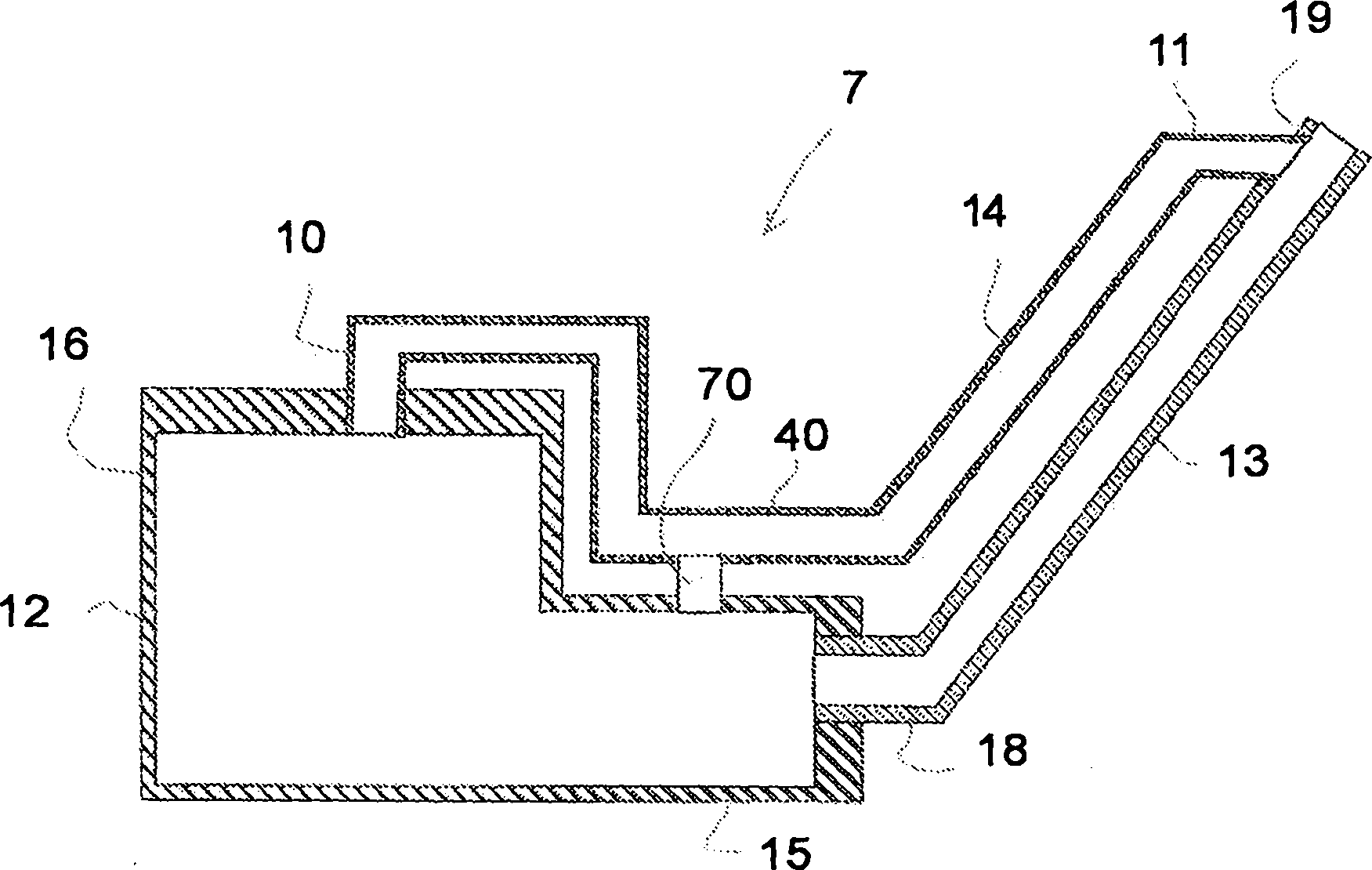
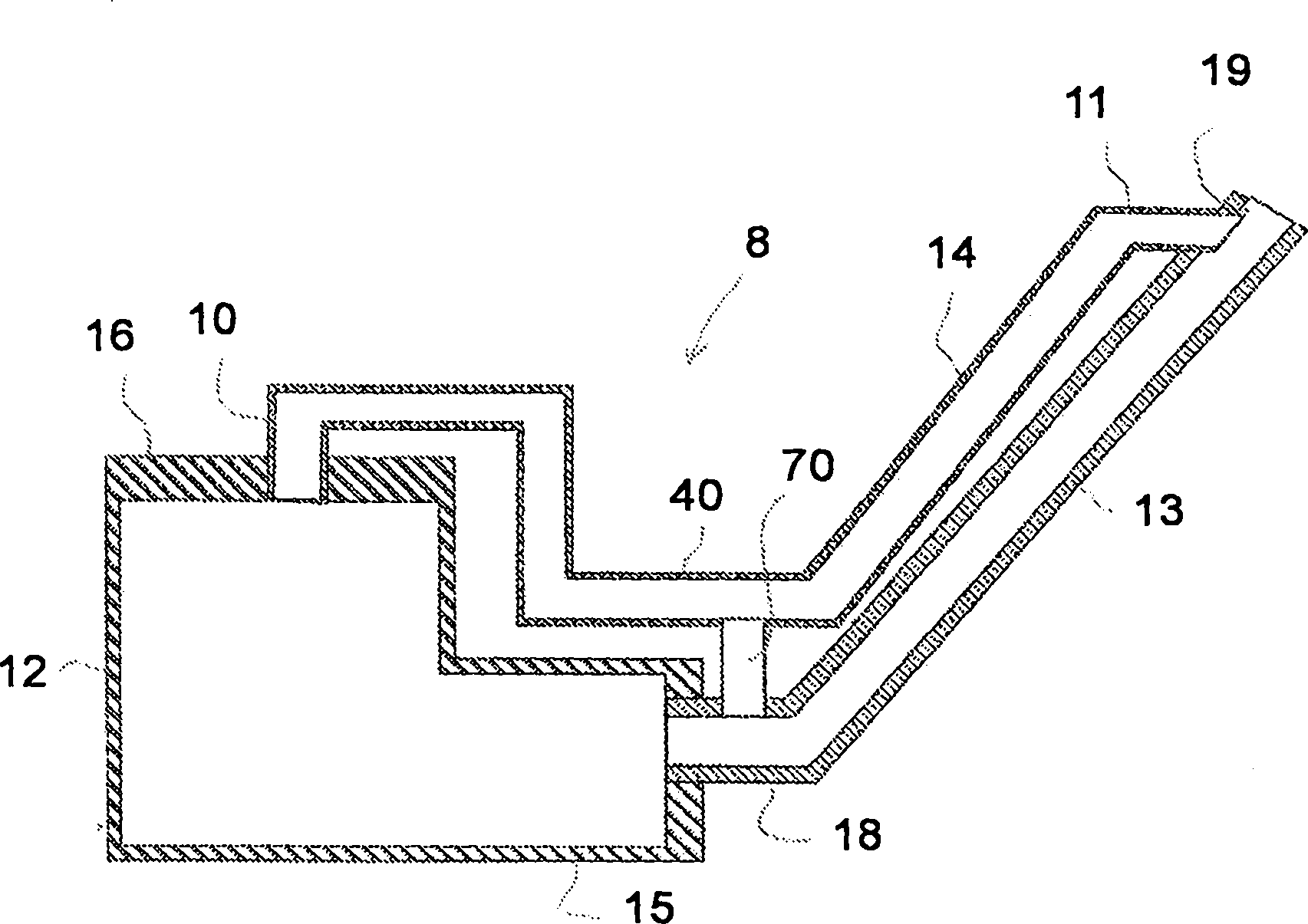
[0020] figure 1 and figure 2 Devices 7 and 8 are shown for filling a tank 12 for supplying liquid to components (not shown) of the motor vehicle. The component of the motor vehicle is in particular an exhaust system converter.

[0021] figure 1 and figure 2 The devices in are used in particular for selective catalytic reduction exhaust system converters (often abbreviated as "SCR" converters by the English acronym).

[0022] Tank 12 contains a reducing agent that reduces nitrogen oxides NOx emitted by the vehicle's internal combustion engine (not shown). The reducing agent is, for example, a liquid containing 30-35% diluted urea in demineralized water. A dose of liquid is normally taken from tank 12 for delivery from a transfer conduit to an injector mounted on the converter of the exhaust system. The injected dose of liquid (NH2-CO-NH2) allows to substantially convert the predetermined amount of nitrogen monoxide and nitrogen dioxide emitted by the engine into water (...


PUM


Abstract

In order to fill a tank (12) of a motor vehicle with a liquid, particularly for a selective catalytic reduction system, a device (7) of the invention includes a filling tube (13) that comprises a bottom end (18) penetrating into the tank (12) and a top end (19) for receiving the liquid so as to fill the tank (12). A ventilation duct (14) comprises an inlet end (10) penetrating into a top portion (16) of the tank (12), an outlet end (11) penetrating into the tube (13) near the top end (19), and a lower section (40) located at a first structural level below the inlet and outlet ends (10, 11). A stationary head-loss generating element (70, 71, 72) places the lower section (40) in communication with a cavity (15) located at a second structural level below the first structural level.

Description

technical field [0001] The invention relates to a device allowing filling of a motor vehicle tank. More specifically, the invention relates to a device designed to supply a urea-containing liquid to a catalytic converter of a motor vehicle. Background technique [0002] Typically, such devices comprise a tank for containing the liquid, such as that described in document EP2131020. According to conventional practice in the art, the tank is filled from the top. This type of filling is particularly suitable for gradually pouring liquid directly from the bottle into the opening formed in the upper part of the tank. Air or other gases contained in the tank above the liquid then escape through the opening, in close contact with the flow of liquid poured in the opposite direction. [0003] This mode of filling is no longer applicable when the tank is not sufficiently accessible to allow filling by pouring liquid directly into the tank. This method of filling is also not suitabl...

Claims


Application Information

Patent Timeline
IPC IPC(8): F01N3/20B60K15/035
CPCY02T10/24B60K13/04F01N2610/1466B67D7/42F01N3/2066B60K15/035F01N2610/1406F01N2610/1413Y02A50/20Y02T10/12
Inventor D·杜托-普瓦鲁F·马尔托A·纳佐恩德
Owner RENAULT SA
Why Eureka
Try Eureka