Operation support device, touch panel device, and touch panel input system
a technology of operation support and touch panel, which is applied in the direction of instruments, computing, electric digital data processing, etc., can solve the problem that the input operation equivalent to the touch operation of pressing a finger against a touch panel cannot be performed correctly, and achieve the effect of correct recognition of input operations
- Summary
- Abstract
- Description
- Claims
- Application Information
AI Technical Summary
Benefits of technology
Problems solved by technology
Method used
Image

Examples
first embodiment
(1-6) Modification of First Embodiment
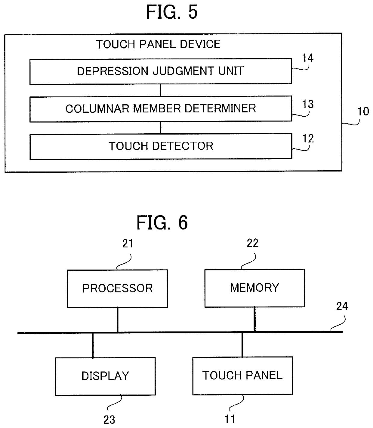
[0063]In the above description, the touch panel device 10 may judge a depressing direction of the operation knob 100 based on the detection values of the electrostatic capacitance at the positions of the columnar members 121, 122 and 123. FIG. 8 shows a touch panel device 10a further including a depressing direction judgment unit 15 that judges the depressing direction of the operation knob 100. The configuration in FIG. 8 differs from the configuration in FIG. 5 in that the depressing direction judgment unit 15 is added. The rest of the configuration in FIG. 8 is the same as that in FIG. 5.
[0064]The depressing direction of the operation knob 100 means the direction of force in a direction parallel to the touch panel 11 when the force in the direction parallel to the touch panel 11 is applied to the operation knob 100 while depressing the operation knob 100 towards the touch panel 11. In cases where the operation knob 100 does not move in parall...
second embodiment
(2) Second Embodiment
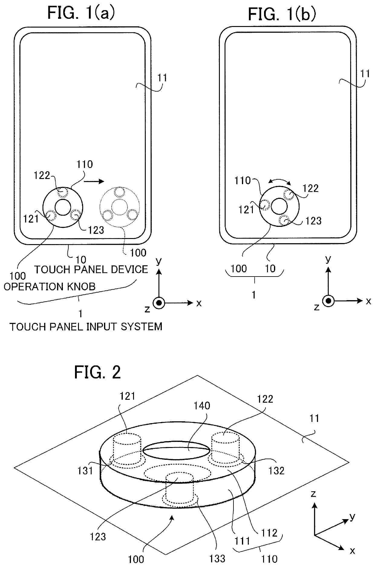
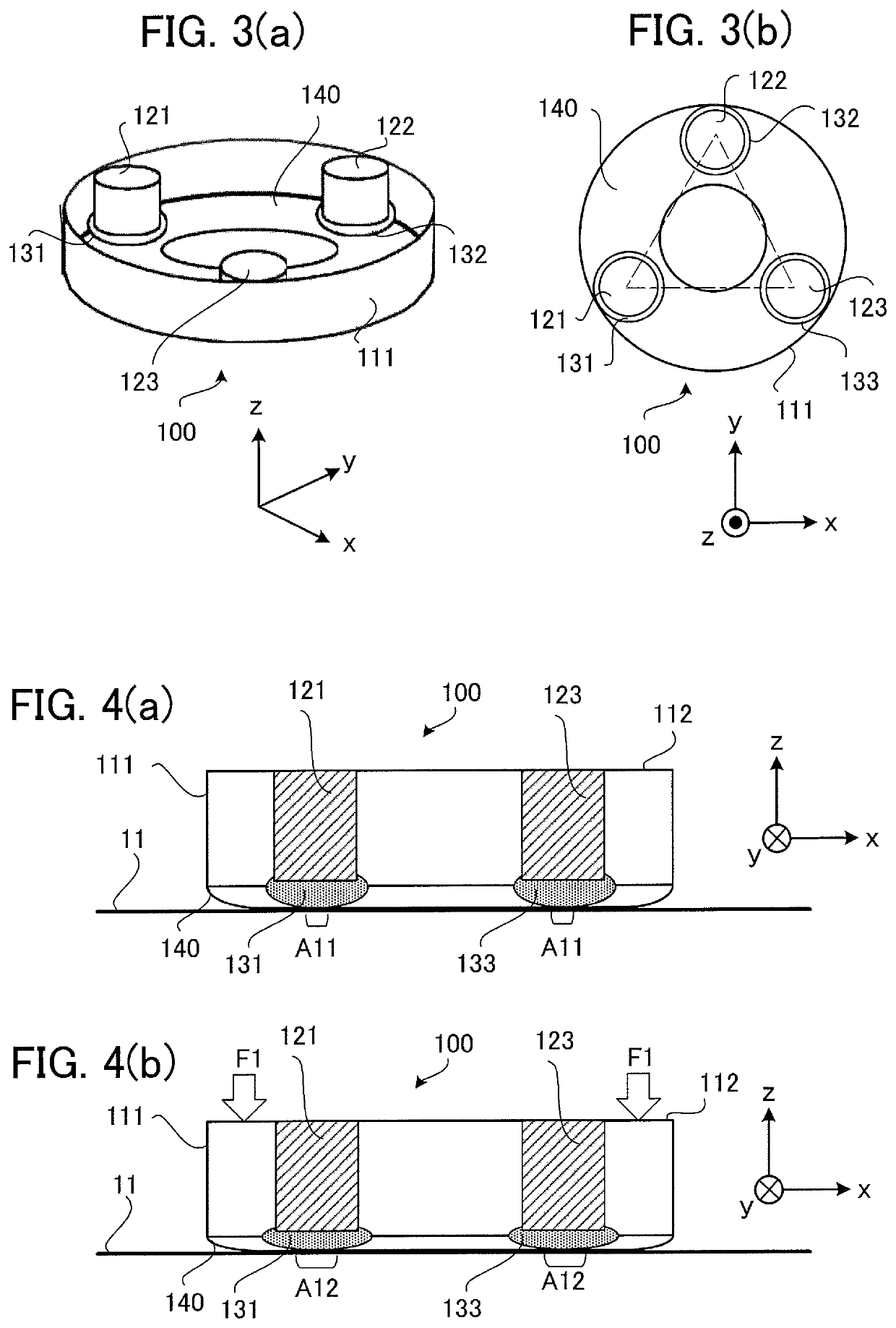
[0071]In the above first embodiment, the description is given of an example in which the touch panel device 10 judges the start and the end of depressing the operation knob 100 by using the change in the electrostatic capacitance (i.e., the change in the detection values of the electrostatic capacitance, the change in the detection positions of the electrostatic capacitance, etc.) due to the change in the contact regions of the lower surface part 140 and the cushion members 131, 132 and 133 as the deforming members of the operation knob 100 (i.e., the change in the contact area, the change in the contact positions, etc.). In a second embodiment, a description will be given of an example in which the touch panel device 10 includes a lower surface part 240 that is an elastic member as a defaming member of an operation knob 200 and judges the start and the end of depressing the operation knob 200 by using the change in the electrostatic capacitance (i.e., the chang...
third embodiment
(3) Third Embodiment
[0084]In the above first and second embodiments, the description has been given of examples in which the start and the end of depressing the operation knob 100 or 200 are judged by using the change in the detection values of the electrostatic capacitance at the positions of the columnar members 121, 122 and 123 or the columnar members 221, 222 and 223 forming the operation knob 100 or 200. However, the detection values of the electrostatic capacitance in commercially available touch panels are generally not published, and thus there are cases where the depression judgment cannot be made correctly in a touch panel input system as a combination of the operation knob 100 or 200 in the first or second embodiment and a commercially available touch panel. Therefore, in a third embodiment, a description will be given of an example in which the positions of columnar members of an operation knob 300 are detected by using the change in the touch positions (specifically, mo...
PUM
 Abstract
Description
Claims
Application Information
 - R&D
- Intellectual Property
- Life Sciences
- Materials
- Tech Scout
- Unparalleled Data Quality
- Higher Quality Content
- 60% Fewer Hallucinations
Browse by: Latest US Patents, China's latest patents, Technical Efficacy Thesaurus, Application Domain, Technology Topic, Popular Technical Reports.
© 2025 PatSnap. All rights reserved.Legal|Privacy policy|Modern Slavery Act Transparency Statement|Sitemap|About US| Contact US: help@patsnap.com