Ink discharge complementing method and printing apparatus

a technology of complementing method and ink discharge, which is applied in the direction of printing mechanism, visual presentation using printer, instruments, etc., to achieve the effect of suppressing the formation of wrinkles in the ink discharge range and simple control

Active Publication Date: 2022-03-08
DAINIPPON SCREEN MTG CO LTD
View PDF9 Cites 6 Cited by
  • Summary
  • Abstract
  • Description
  • Claims
  • Application Information

AI Technical Summary

Benefits of technology

[0007]This invention was developed in view of the above problem and aims to provide a technique capable of dealing with a defective nozzle by a simple control.
[0017]As described above, according to the invention, the formation of wrinkles in an ink discharge range can be suppressed in printing an image by discharging ink to a printing medium while conveying the printing medium in a conveying direction.

Problems solved by technology

However, in a method of JP 2015-150751A, a cumbersome control of preparing a table for each image density and properly using these tables is executed to change the amount of the ink discharged from the adjacent nozzles according to a density of an image to be printed.

Method used


Image

  • Ink discharge complementing method and printing apparatus
  • Ink discharge complementing method and printing apparatus
  • Ink discharge complementing method and printing apparatus

Examples


Embodiment Construction

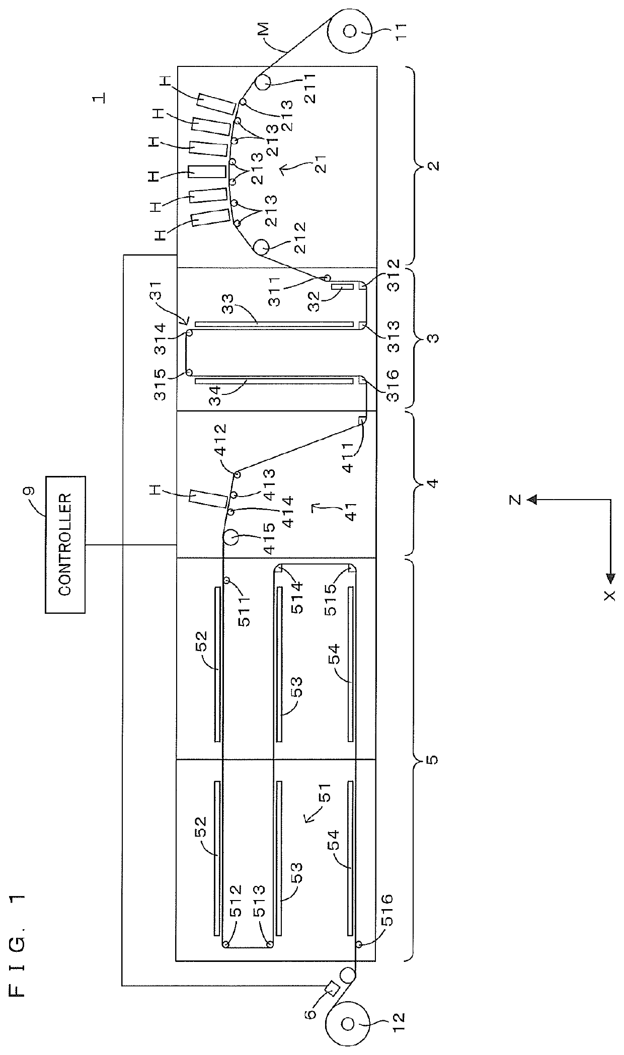
[0032]FIG. 1 is a front view schematically showing an example of a printing apparatus according to the invention. In FIG. 1, a horizontal direction X and a vertical direction Z are shown as appropriate. As shown in FIG. 1, the printing apparatus 1 has a configuration with a printer 2, a dryer 3, a printer 4 and a dryer 5 arrayed in this order in the horizontal direction X (array direction). This printing apparatus 1 dries a printing medium M printed in the printer 2 in the dryer 3 and further dries the printing medium M printed in the printer 4 in the dryer 5 while the printing medium M in the form of an elongated belt is conveyed in a roll-to-roll manner from an unwinding roll 11 to a winding roll 12. Note that various materials such as paper or films can be utilized as the printing medium M. Further, out of both surfaces of the printing medium M, the surface on which images are to be printed is referred to as a front surface and the surface opposite to the front surface is referre...


PUM


Abstract

The conversion of the dot percentages using the first conversion table Td1 and the second conversion table Td2 is performed for the gradation data Dh by the defective nozzle corrector 95. Here, the first conversion table Td1 converts the dot percentages of the pixels Px corresponding to the normal nozzles Nn having no discharge defect by the first rate Rd1 lower than 100%, and the second conversion table Td2 converts the dot percentages of the pixels Px corresponding to the surrounding nozzles Na located around the defective nozzle Nd by the second rate Rd2 higher than the first rate Rd1. Then, the shading correction is performed for the defect complemented gradation data Dc obtained by converting the dot percentages in this way by the shading corrector 96.

Description

CROSS REFERENCE TO RELATED APPLICATION[0001]The disclosure of Japanese Patent Application No. 2020-054013 filed on Mar. 25, 2020 including specification, drawings and claims is incorporated herein by reference in its entirety.BACKGROUND OF THE INVENTION[0002]1. Field of the Invention[0003]This invention relates to a technique for complementing an ink discharge defect of a defective nozzle, out of a plurality of nozzles of a discharge head.[0004]2. Description of the Related Art[0005]A printing technique is known which prints an image on a printing medium by discharging ink to the printing medium from a plurality of nozzles of a discharge head. In such a printing technique, a defective nozzle having an ink discharge defect may occur due to the clogging of the solidified ink in the nozzle or the like. In such a case, since the ink is not discharged at a position corresponding to the defective nozzle, a white streak is caused in an image. Accordingly, in JP 2015-150751A, the occurrence...

Claims


Application Information

Patent Timeline
Patent Type & Authority Patents(United States)
IPC IPC(8): G06K15/02G06K15/10B41J2/21
CPCG06K15/027B41J2/2142G06K15/102G06K15/1881B41J2/2139H04N1/4078B41J2/2146B41J2025/008H04N1/4015B41J29/393
Inventor FUKUI, KAZUKI
Owner DAINIPPON SCREEN MTG CO LTD
Why Eureka
Try Eureka