Operating a service provider network node

a service provider network and node technology, applied in the direction of data switching networks, digital transmission, electrical devices, etc., can solve the problems of affecting performance, difficult and/or inefficient routing for the control plane processing part, and relatively complicated routing processes

Active Publication Date: 2022-03-08
METASWITCH NETWORKS LTD
View PDF7 Cites 0 Cited by
  • Summary
  • Abstract
  • Description
  • Claims
  • Application Information

AI Technical Summary

Benefits of technology

[0005]It may be desirable for a service provider network node to be able to send locally-originated control packets to other nodes in the context of the VRF. For example, it may be desirable for a first PE node to test the connectivity and / or reachability of a CE node that is connected to a second, different PE node. This may require the ability for the control plane processing part of the first PE node to generate packets with an appropriate MPLS label stack, and to route such packets correctly. However, routing processes may be relatively complicated and / or computationally expensive. Routes may also be difficult and / or inefficient for the control plane processing part to manage, store and / or update. This can impact performance, and may require a relatively large amount of state in the control plane processing part.

Problems solved by technology

However, routing processes may be relatively complicated and / or computationally expensive.
Routes may also be difficult and / or inefficient for the control plane processing part to manage, store and / or update.
This can impact performance, and may require a relatively large amount of state in the control plane processing part.

Method used


Image

  • Operating a service provider network node
  • Operating a service provider network node
  • Operating a service provider network node

Examples


Embodiment Construction

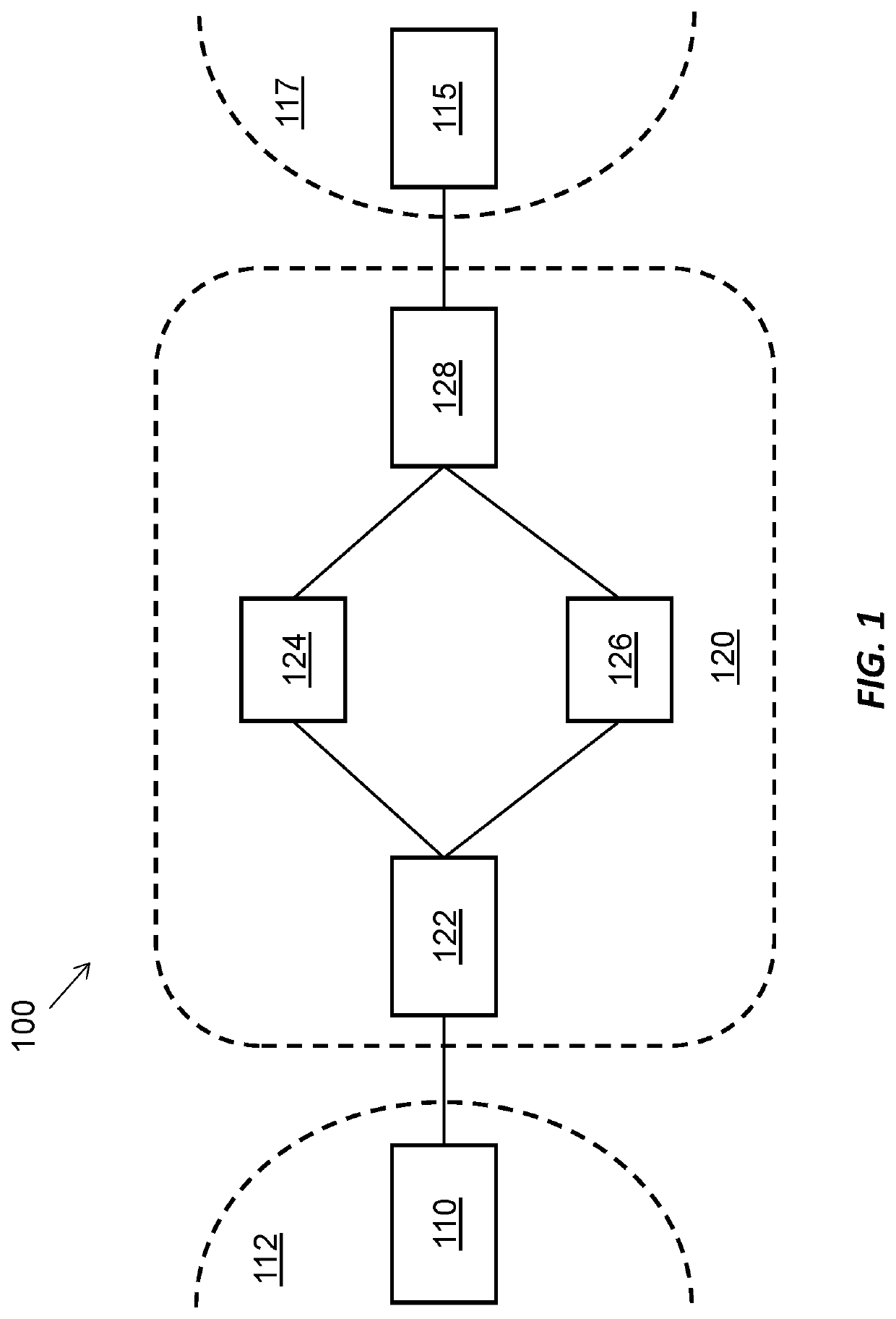
[0021]Referring to FIG. 1, there is shown an environment 100, according to embodiments. The environment 100 includes a first customer network node 110 and a second customer network node 115. The first customer network node 110 is in a first part 112 of a first customer network, and the second customer network node 115 is in a second part 117 of the customer network. The two parts 112, 117 of the customer network are geographically separated, according to embodiments. That is, the first and second customer network nodes 110, 115 are located at different customer sites. As such, the second customer network node 115 is arranged at a remote location relative to the first customer network node 110. In alternative embodiments, the two parts 112, 117 of the customer network are co-located. Therefore, in such embodiments, the first and second customer network nodes 110, 115 may be located at a same site. The first and second customer network nodes 110, 115 may be unable to directly communic...


PUM


Abstract

Certain aspects of the present disclosure provide a method of operating a service provider network node in a service provider network, comprising: establishing an interface between a control plane processing part and a data plane processing part for routing of control packets at the data plane processing part; at the control plane processing part, generating a control packet for routing through the service provider network; and at the control plane processing part, sending the control packet to the data plane processing part via the interface, to cause the data plane processing part to route the control packet through the service provider network using the one or more routing tables maintained by the data plane processing part in response to receiving the control packet from the control plane processing part via the interface.

Description

CROSS REFERENCE TO RELATED APPLICATIONS[0001]This application claims priority to United Kingdom (GB) Application No. 1909253.5, filed Jun. 27, 2019, the entire contents of which are incorporated herein by reference.INTRODUCTION[0002]The present disclosure relates to operating a service provider network node. In particular, but not exclusively, the present disclosure relates to operating a service provider network node in a service provider network that provides connectivity between customer nodes of a customer network.[0003]A customer (or enterprise) network may be divided across multiple, geographically distributed, sites. A service provider network can be used to provide connectivity between such sites, e.g. through use of a virtual private network (VPN). This is achieved by tunneling customer-originated traffic through the service provider network (which may, for example, be part of the public Internet). An example of a VPN that can be provided by a service provider is a layer 3 ...

Claims


Application Information

Patent Timeline
Patent Type & Authority Patents(United States)
IPC IPC(8): H04L12/741H04L12/713H04L12/931H04L49/00H04L45/021H04L45/00H04L45/586
CPCH04L49/309H04L45/021H04L45/54H04L45/586H04L49/70H04L45/50H04L43/10H04L43/00H04L45/22H04L45/60
Inventor ELDER, ALANHARRISON, JONBALLS, STEVE
Owner METASWITCH NETWORKS LTD
Why Eureka
Try Eureka