Submersible power plant

a technology of submerged power plant and rudder, which is applied in the direction of sea energy generation, waterborne vessels, underwater equipment, etc., can solve the problems of flow separation and vortex creation, and achieve the effect of increasing the efficiency of power production, ensuring safety, and increasing the protection of the rudder

Active Publication Date: 2017-01-12
MINESTO
View PDF3 Cites 0 Cited by
  • Summary
  • Abstract
  • Description
  • Claims
  • Application Information

AI Technical Summary

Benefits of technology

[0019]Further, by having a closed wing with hydrodynamically shaped hydrodynamic elements, a similar effect as for horizontal wings is achieved, i.e. no wingtip vortices are created from the vertical surfaces which may be the case if winglets were used which did not close the wings.
[0020]The vehicle may comprise a nacelle comprising a generator, the generator being attached to a turbine, where the nacelle is positioned between the first wing and the second wing. By equipping the vehicle with a nacelle comprising a generator attached to a turbine the vehicle can produce power by means of the turbine rotating when the vehicle travels through the fluid, thereby rotating the generator. By having a vehicle with a wing configuration according to the invention the vehicle can be made smaller while maintaining efficiency or the efficiency of the power production can be increased by maintaining the size of the vehicle. It is also possible to extract power from other parts of the power plant, for instance by attaching a linear generator or a winch to the tether. Power is then generated from the variation in distance between the vehicle and the foundation during the trajectory. A vehicle according to the invention further allows for more protection for the rudder as most or the entire rudder is located between the wings.
[0021]The first wing and the second wing can have the same shape or have different shape. In case the first wing and the second wing have the same wing shape, this leads to an easier and less expensive production process as there is no customization required for any of the wings. It is also less expensive to hold replacement wings as a single type of wing can replace both the first wing and the second wing. In case the first wing and the second wing have different wing shapes it is possible to tailor the hydrodynamic properties of the vehicle for specific site conditions, thereby further increasing the efficiency of the vehicle. It is also possible to tailor the vehicle so that the power plant can be installed on sites with shallower depth than a prior art power plant as the turning radius can be decreased. In addition to having the same or different shapes, the first wing and the second wing can have the same planform area or different planform areas further increasing the tailoring possibilities.
[0022]The pitch angles of the first wing and the second wing can be adjusted relative each other. This enables steering in pitch direction of the vehicle. Besides allowing increased steering ability of the vehicle, the wings may also be pivoted to an emergency brake position wherein the vehicle is not propelled by the fluid stream. In the emergency brake position the pitch angle of the wings are adjusted to a position in which the forces acting on each wing by the incoming fluid stream are balanced out or closed to balanced out, leading to that the vehicle lies essentially motionless in the water. The emergency brake can be used if the vehicle malfunctions and needs to be repaired or if the velocity of the vehicle exceeds a design velocity, which may cause structural damage to the vehicle or other parts of the power plant.
[0023]The tether may be attached to the vehicle by means of struts. Front struts are attached to the first wing and a rear strut is attached to the second wing. By dividing the wings in a longitudinal direction it is possible to attach struts which attach the tether to the vehicle to both wings. Distributing the wing area in a longitudinal direction gives rise to an increase of pitch inertia, where pitch is a rotation around an axis being parallel to the wing span. The increase in pitch inertia is caused by two phenomena. Due to that mass is moved away from the centre of gravity, an increase in inertia is caused. This can be derived from rigid body dynamics. An additional increase in inertia arises from that the surface which moves through the water is increased. Accelerating a body in a fluid adds inertia due to that more fluid need to be displaced; this is known as added mass. Separating the first wing and the second wing in a longitudinal direction gives rise to a substantial increase of added mass when pitching the vehicle. One advantage with this configuration is that the need for a stabilizing torque from the tether is reduced. This allows for use of shorter struts which reduces the drag from the struts. By attaching the front struts to the first wing and the rear strut to the second wing the vehicle will experience further increased pitch stability due to that the distance between the front and rear struts is increased. The increase in distance between the attachment points for the front and rear struts increases the moment of inertia around the point where the struts attach to the tether. This further allows for use of shorter struts to be used in this configuration. Shorter struts simplify installation and maintenance of the vehicle. Reduction in drag is caused by the decreased area of the shorter struts.
[0024]The wings can for instance be made of metal, various laminates or a combination thereof. Carbon fibre laminate and glass fibre laminate are two possible laminate options. Other materials are also conceivable. By shortening the wing span the use of a lighter material such as a laminate is made possible. A smaller wing also leads to a lower material cost for the vehicle, as for instance thinner walls or beams can be made of a less expensive material such as glass fibre laminate. Using glass fibre laminate may further decrease risks and design costs concerning bimetallic / galvanic corrosion of attached / built in metal parts in the prior art vehicle.

Problems solved by technology

Large pressure gradients are thereby created leading to problems with vortex creation and flow separation.

Method used


Image

  • Submersible power plant
  • Submersible power plant
  • Submersible power plant

Examples


Embodiment Construction

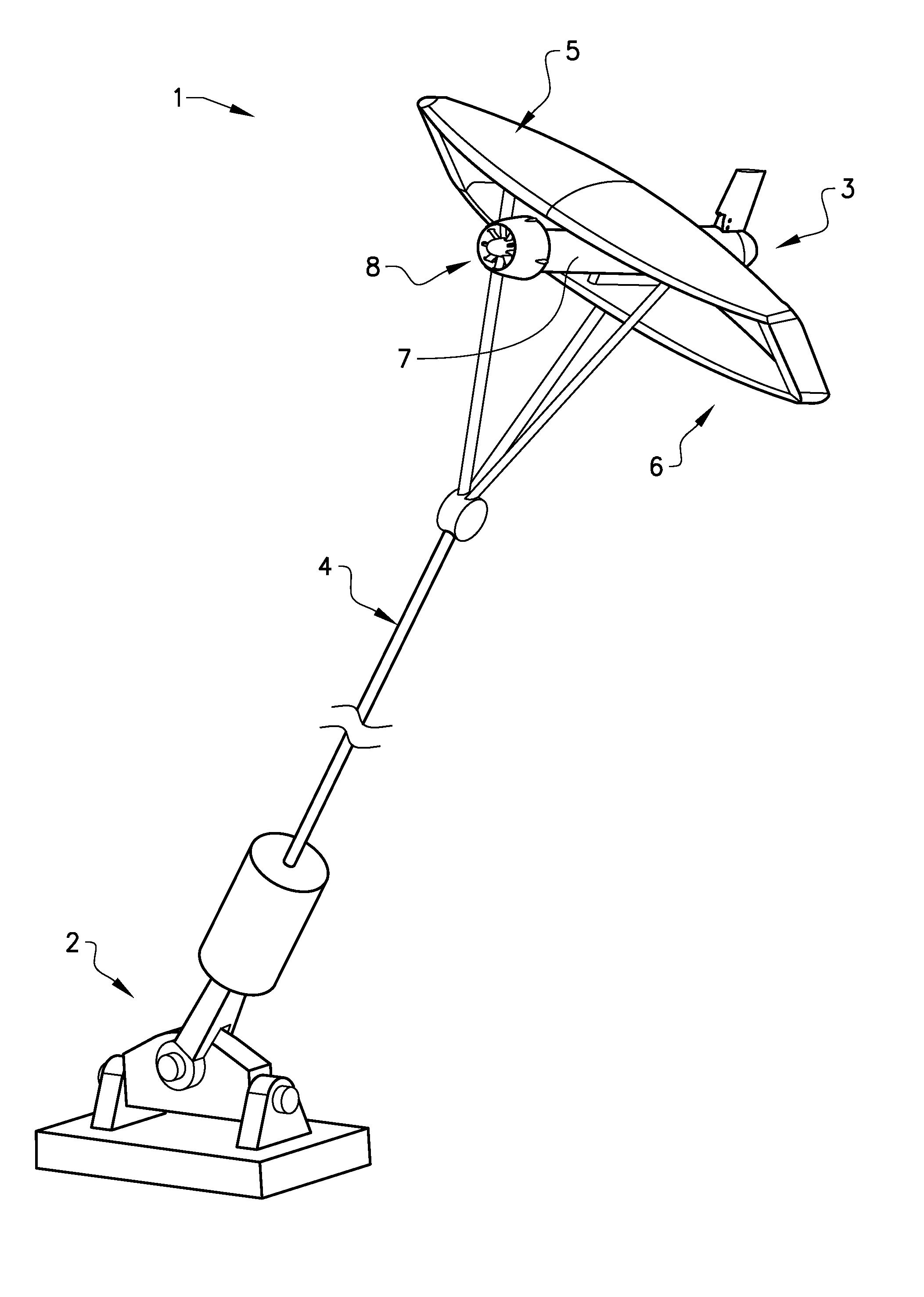
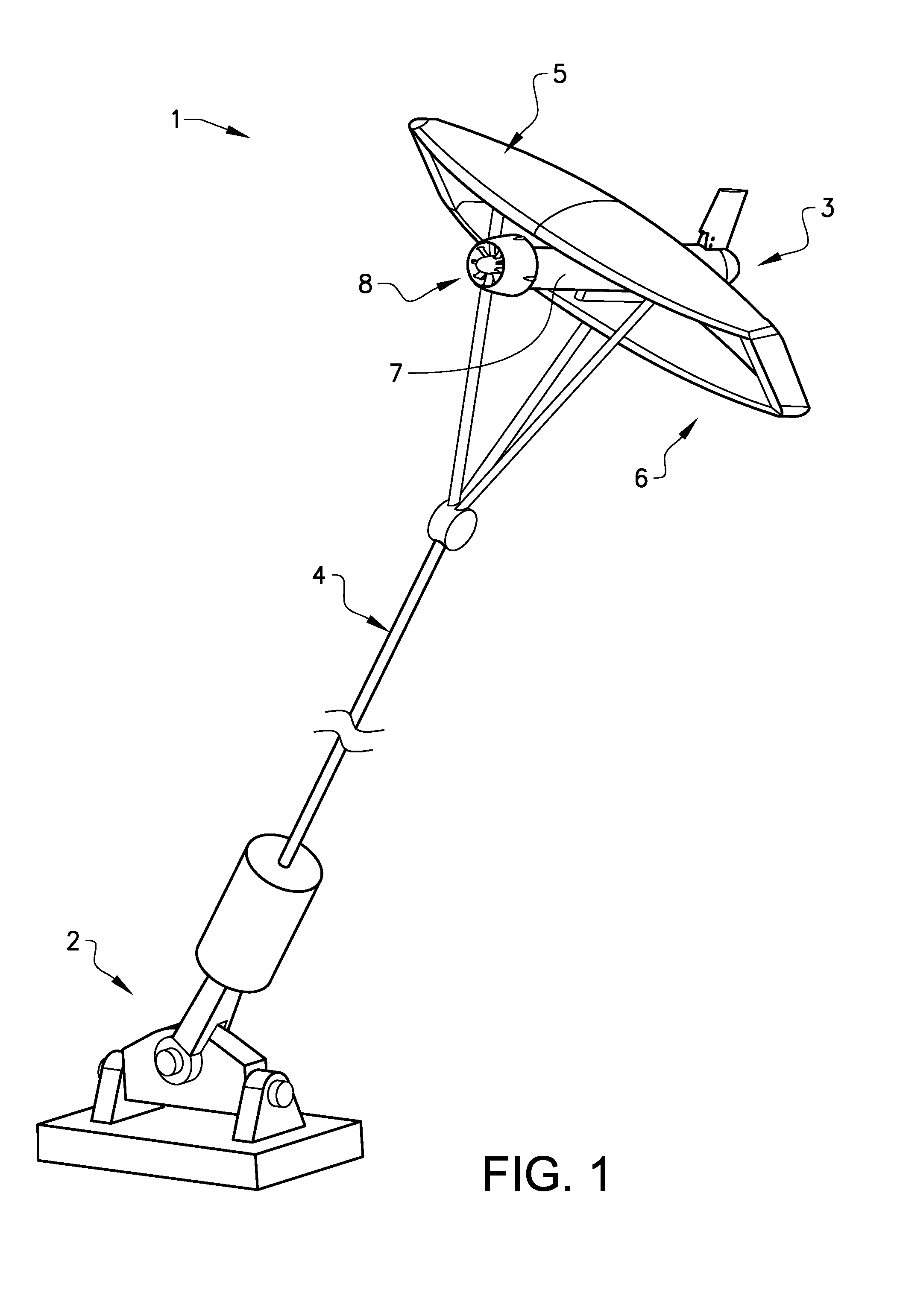
[0030]FIG. 1 schematically shows a power plant 1 according to the invention. The power plant 1 comprises a structure 2 and a vehicle 3. The vehicle 3 is arranged to be secured to the structure 2 by means of at least one tether 4. The vehicle 3 comprises a first wing 5 and a second wing 6. The vehicle 3 is arranged to move in a predetermined trajectory by means of a fluid stream passing the wings of the vehicle 3. The vehicle 3 further comprises a nacelle 7 comprising a generator. The nacelle 7 is attached to a turbine 8. The nacelle 7 is positioned between the first wing 5 and the second wing 6. In FIG. 1 the vehicle 3 comprises a closed wing. The closed wing is described in further detail below. It is also possible for the vehicle 3 to have two separate wings without winglets or two separate wings, with one or both wing having winglets. In FIG. 1 the structure 2 is seen to be placed below the vehicle 3, this can for instance be at the bottom of the ocean or of a sea. It is also pos...


PUM


Abstract

The invention relates to a submersible power plant. The power plant comprises a structure and a vehicle. The vehicle is arranged to be secured to the structure by means of at least one tether. The vehicle is arranged to move in a predetermined trajectory by means of a fluid stream passing the vehicle. The vehicle comprises a first wing and a second wing, where the first wing is arranged at a first distance D1 from the second wing in a longitudinal direction, and the first wing is arranged at a second distance D2 from the second wing in a lateral direction.

Description

CROSS-REFERENCE TO RELATED APPLICATION[0001]This application is a U.S. National Stage patent application of PCT / SE2014 / 050156, filed on Feb. 7, 2014, the entire content of which is incorporated herein by reference.TECHNICAL FIELD[0002]The invention relates to a submersible power plant. The power plant comprises a structure and a vehicle. The vehicle is arranged to be secured to the structure by means of at least one tether.[0003]The vehicle is arranged to move in a predetermined trajectory by means of a fluid stream passing the wing.BACKGROUND ART[0004]A submersible power plant is known in the art from EP 1816345. The power plant in EP 1816345 comprises a vehicle comprising one wing with a nacelle comprising a turbine and generator attached to the wing. The power plant is arranged to move in a predetermined trajectory by means of a fluid stream passing the wing.[0005]A winged body moving through a fluid, experiences induced drag. The induced drag reduces the efficiency of the wing a...

Claims


Application Information

Patent Timeline
Patent Type & Authority Applications(United States)
IPC IPC(8): F03B13/10B63G8/00
CPCF03B13/10F05B2220/32B63G8/001F03B17/061F05B2240/917F05B2240/9174Y02E10/30F03B13/26Y02E10/20
Inventor MARZELIUS, OLOFDOLERUD, ERIK
Owner MINESTO
Why Eureka
Try Eureka