Continuously variable transmission and transmission system

a transmission system and transmission technology, applied in the direction of machines/engines, liquid fuel engines, gearing, etc., can solve the problems of limited transmission ratio between the rotational speed of the engine and the rotational speed of the wheels, push belts are prone to slippage, and push belt transmissions are only used in relatively light applications. , to achieve the effect of compact transmission and significant simplified transmission design

Active Publication Date: 2022-03-22
HCVTRANSMISSION BV
View PDF9 Cites 0 Cited by
  • Summary
  • Abstract
  • Description
  • Claims
  • Application Information

AI Technical Summary

Benefits of technology

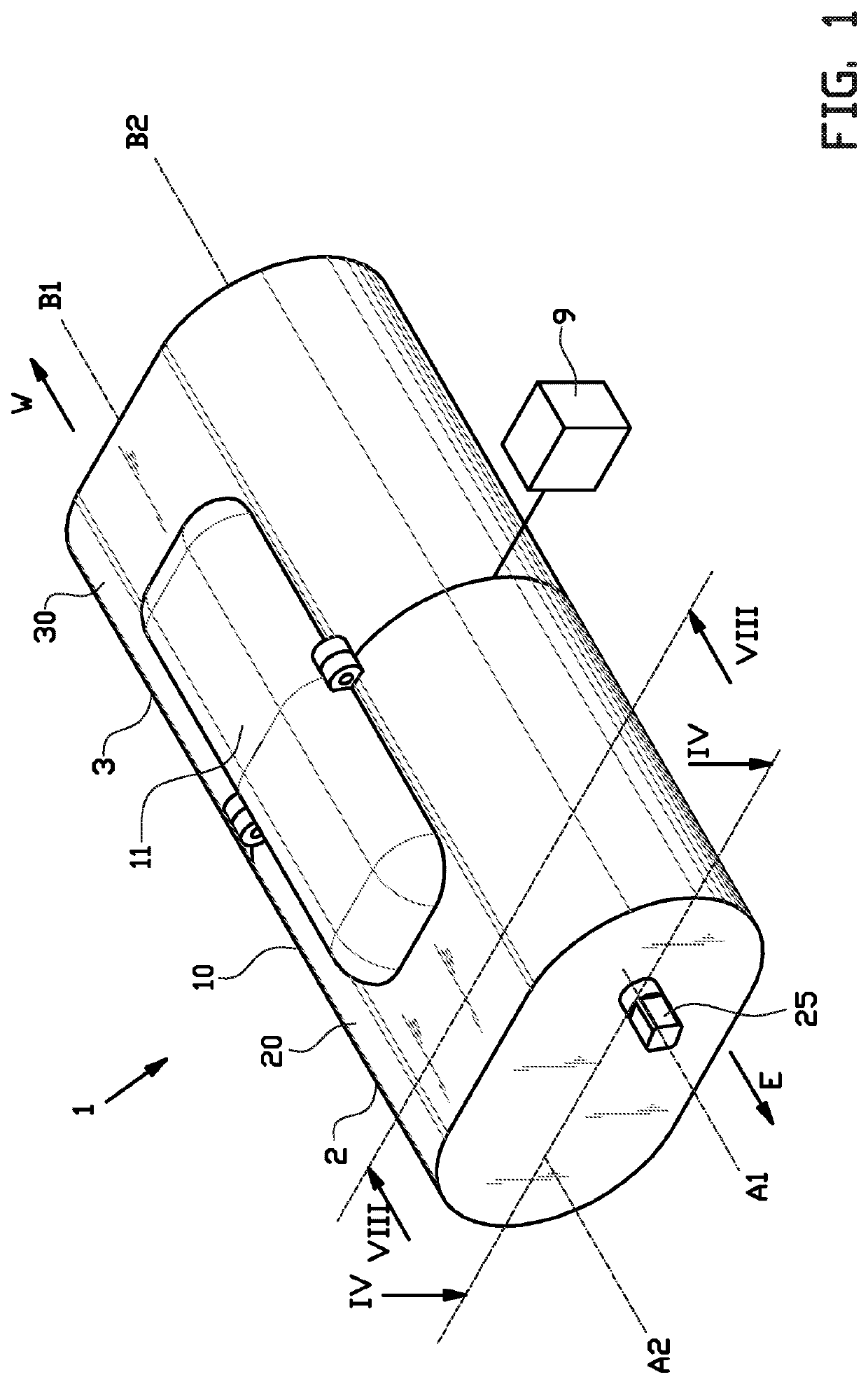
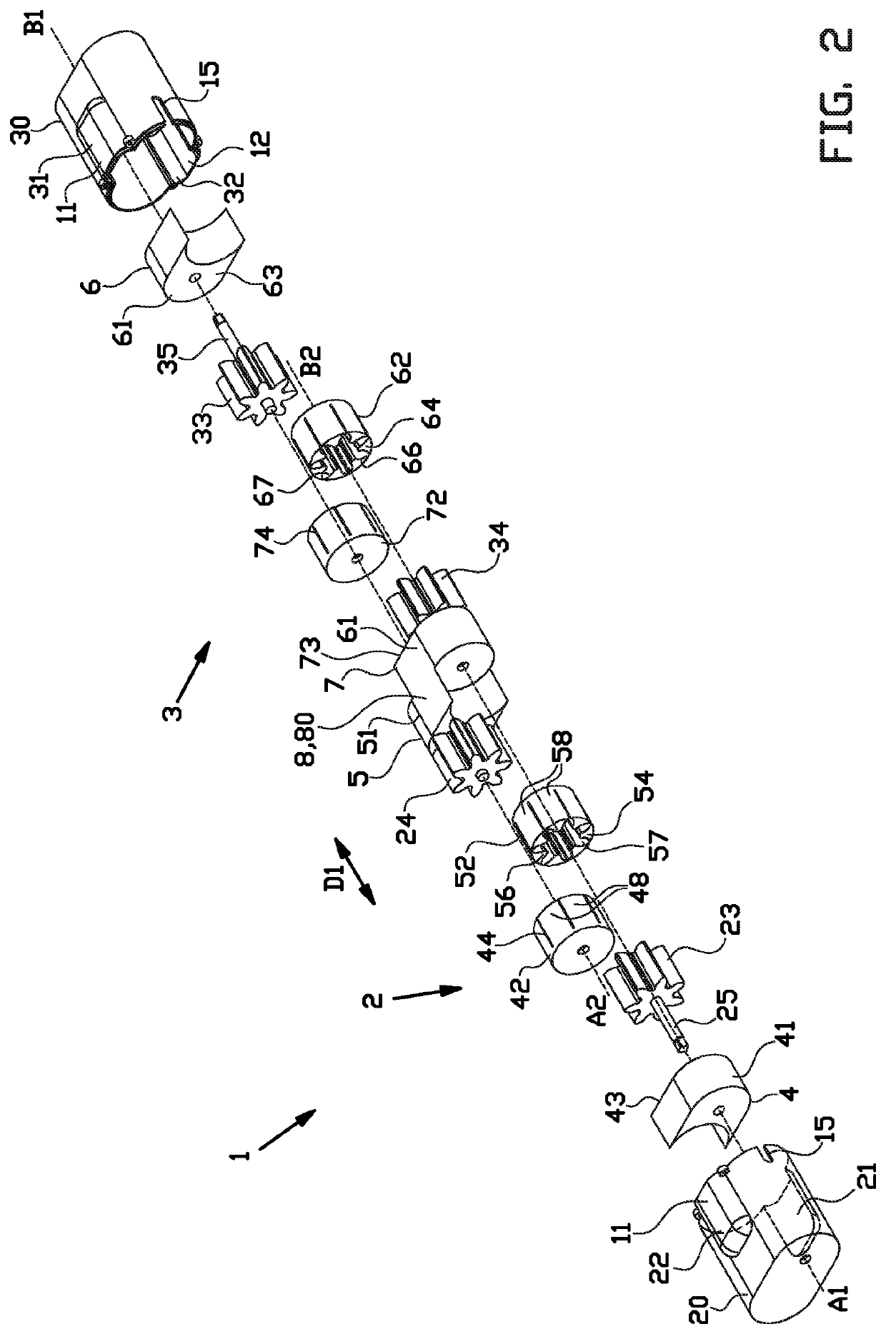
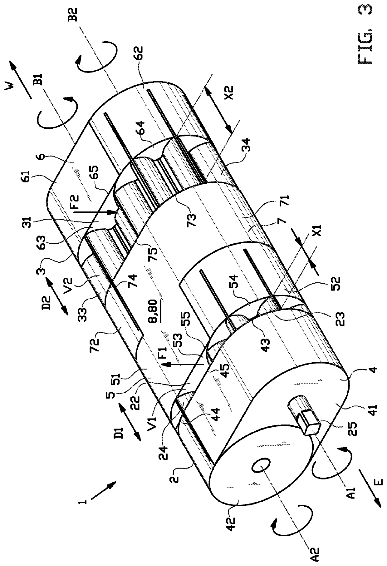
[0008]By adjusting the pump volumes in an inverse correlation to each other, with the pump volumes being in fluid communication with each other, the transmission ratio between the rotational speed of the first gear pump and the rotational speed of the second gear pump can be effectively adjusted. By using a fluid as the medium to transmit power in a substantially closed hydraulic circuit, slipping can be reduced, prevented or even eliminated. The transmission according to the present invention can thus be used in a particularly effective and / or efficient manner in both light and heavy load applications, e.g. in vehicles such as trucks. The transmission according to the present invention can further be used to optimize a power source, e.g. a combustion engine or an electrical engine, to run at its optimal rotational speed.
[0042]In an embodiment thereof the housing at least partially defines the pump volume of the first gear pump and the pump volume of the second gear pump. Said housing can thus be used to both contain and seal both gear pumps, without requiring an additional housing for one of said purposes.

Problems solved by technology

However, push belts are prone to slipping, especially in heavy load applications, e.g. in trucks.
Hence, push belt transmissions are only used in relatively light applications.
Moreover, the transmission ratio between the rotational speed of the engine and the rotational speed of the wheels is limited to the gear ratios as defined by the planetary gears.
Hence, although the speed and torque may be continuously adjusted, the choice of transmission ratios is limited.

Method used


Image

  • Continuously variable transmission and transmission system
  • Continuously variable transmission and transmission system
  • Continuously variable transmission and transmission system

Examples


second embodiment

[0095]FIGS. 9-15 show an alternative continuously variable transmission 101 according to the invention. Said alternative transmission 101 differs from the aforementioned transmission 1 in that it comprises a first gear pump 102 with a telescopic first gear 123, a telescopic second gear 124 and a second gear pump 103 with a telescopic third gear 133 and a telescopic fourth gear 134. Hence, the alternative transmission 101 does not require any receptacles as in the previously discussed transmission. The overlap distance X1, X2 between the meshing telescopic gears 123, 124; 133, 134 is simply adjusted by changing the telescopic length of the telescopic gears 123, 124; 133, 134 in the respective overlap directions D1, D2.

[0096]As best seen in FIG. 10, each telescopic gear comprises a first gear part 126, 136 with a plurality of first gear teeth 127, 137 distributed circumferentially about the respective gear axis A1, A2, B1, B2 and a second gear part 128, 138 with a plurality of second ...

third embodiment

[0102]FIGS. 16-22 show a further alternative continuously variable transmission 201 according to the invention. Said further alternative transmission 201 differs from the previously discussed transmissions 1, 101 in that it comprises a first gear pump 202 and a second gear pump 203 which are internal gear pumps. More in particular, each gear pump 202, 203 comprises a first gear 223, 233 that is an external gear and a second gear 224, 234 that is an internal gear. The external gear 223, 233 has a smaller diameter and less teeth than the internal gear 224, 234. The first gear axis A1, B1 and the second gear axis A2, B2 are offset with respect to each other. Each gear pump 202, 203 further comprises a stationary crescent 226, 236 between the external gear 223, 233 and the internal gear 224, 234. The stationary crescent 226, 236 is stationary in the circumferential direction about the first gear axis A1, B2 to guide the rotation of the external gear 223, 233 about the first gear axis A1...

fourth embodiment

[0112]As shown in FIG. 24, the further alternative transmission 301 further comprises a control member 309 in the form of a knob that is coupled and / or connected to the connecting member 308 for moving said connecting member 308 and the adjustment members 305, 307 associated therewith in the respective overlap directions D1, D2. More in particular, the control member 309 is coupled to or received inside the container 380 of the connecting member 308 to directly drive the movement of the adjustment members 305, 307 in the respective overlap directions D1, D2. In this exemplary embodiment, the control member 309 comprises a base 391 that is coupled to the connecting member 308 and a knob 392 that extends from the base 391 and protrudes through a slot 315 in the housing 310. The knob 392 can be manually operated from outside the housing 310.

[0113]The further alternative transmission 301 further comprises a port member 393 for receiving said base 391. The port member 393 comprises or f...


PUM


Abstract

The invention relates to a continuously variable transmission and a transmission system comprising said continuously variable transmission, wherein the continuously variable transmission comprises a first gear pump and a second gear pump, wherein each gear pump comprises a first gear and a second gear meshing with the first gear over an overlap distance in an overlap direction parallel to the first gear axis, wherein each gear pump further comprises an adjustment member for adjusting the pump volume, wherein the adjustment member of the first gear pump and the adjustment member of the second gear pump are interconnected by a connecting member for adjusting the pump volume of the first gear pump and the pump volume of the second gear pump in an inverse correlation to each other.

Description

BACKGROUND[0001]The invention relates to a continuously variable transmission, in particular for a vehicle, and a transmission system comprising said continuously variable transmission.[0002]Push belts have been widely applied because of their ability to provide a simple yet effective continuously variable transmission. However, push belts are prone to slipping, especially in heavy load applications, e.g. in trucks. Hence, push belt transmissions are only used in relatively light applications.[0003]FR 1.230.990 A discloses a hydraulic variator gear that is operable as a motor. The hydraulic variator gear comprises two rotors which are in mesh with each other between two planes which limit the portion of active teeth. One of the planes is formed at the end of a sleeve which has complimentary inner teeth from those of the rotor, in which the rotor is slidable to increase or decrease the length of the teeth that mesh. A spring is provided to allow for automatic operation of the hydraul...

Claims


Application Information

Patent Timeline
Patent Type & Authority Patents(United States)
IPC IPC(8): F16H61/00F04C2/10F04C2/18F04C14/18F16H39/00F16H61/50F04C11/00
CPCF16H61/0025F04C2/101F04C2/102F04C2/18F04C11/001F04C14/185F16H39/00F16H61/50F16H61/60
Inventor BUIJSMAN, PETRUS JOHANNES
Owner HCVTRANSMISSION BV
Why Eureka
Try Eureka