Power supply and power system having a step-down circuit and an inverse-conversion circuit

a power supply and power system technology, applied in the direction of dc-dc conversion, control systems, dc-ac conversion without reversal, etc., can solve the problems of high dielectric voltage, large switching noise, and inability to us

Active Publication Date: 2022-03-22
FANUC LTD
View PDF11 Cites 0 Cited by
  • Summary
  • Abstract
  • Description
  • Claims
  • Application Information

AI Technical Summary

Problems solved by technology

If the neutral point of the alternating current outputted greatly differs from the earth potential, a high dielectric voltage relative to earth becomes necessary in the load circuit such as a servomotor, and it may not be possible to use due to a dielectric strength voltage deficiency.
In addition, if the neutral point potential greatly differs from the earth potential, the switching noise becomes large and the risk of malfunction increases.
Although technology for power factor improvement and suppressing peak current has been developing as countermeasures, since it leads to higher cost and increased size for realization, it cannot be easily applied.

Method used


Image

  • Power supply and power system having a step-down circuit and an inverse-conversion circuit
  • Power supply and power system having a step-down circuit and an inverse-conversion circuit
  • Power supply and power system having a step-down circuit and an inverse-conversion circuit

Examples


first embodiment

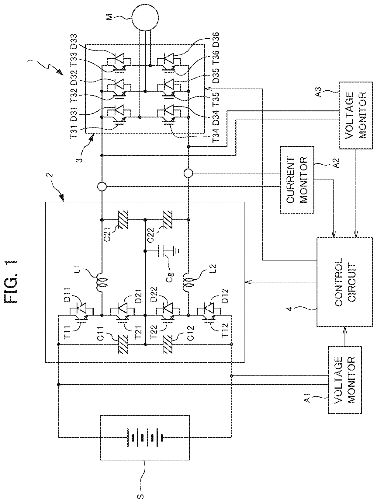
[0020]Each embodiment of the present disclosure will be explained below while referencing the drawings. FIG. 1 is a circuit diagram showing the configuration of a power supply 1 according to the present disclosure.

[0021]The power supply 1 is a device which supplies (powered running) a load (motor M in the present embodiment), by converting the direct current supplied from a primary power source (DC power source S) into three-phase alternating current of a predetermined voltage. In more detail, the power supply 1 is connected to a primary power source S having higher voltage than the rated voltage of the motor M, and supplies the motor M by converting the three-phase alternating current of the primary power source S into three-phase alternating current having voltage equal to the rated voltage of the motor M and frequency equal to the frequency set by external equipment or a user. In addition, the power supply 1 of the present embodiment is configured so as to be able to convert the ...

second embodiment

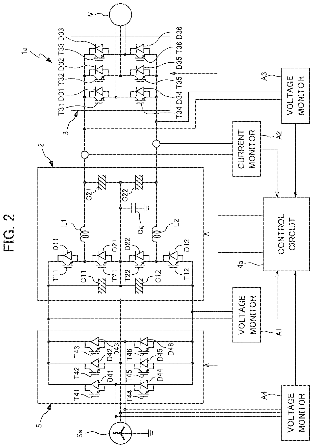
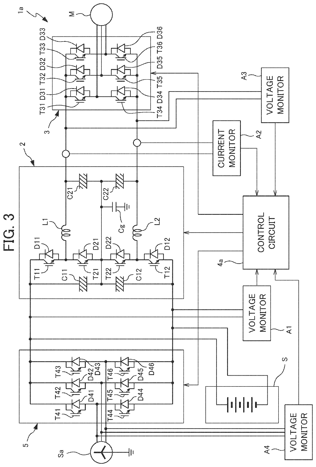
[0037]FIG. 2 is a circuit diagram showing the configuration of a power supply 1a according to the present disclosure. For the power supply 1a in FIG. 2, the same reference symbols will be assigned to constituent elements which are the same as the power supply 1 in FIG. 1, and redundant explanations will be omitted.

[0038]The power supply 1a of the present embodiment is a device which converts the three-phase alternating current supplied from the primary power source (AC power source) Sa into three-phase alternating current having different voltage and frequency, and supplies (powered running) to the load (motor M in the present embodiment). In more detail, the power supply 1a is connected to the primary power source Sa which is grounded to the neutral point having a voltage of at least the rated voltage of the motor M, converts the three-phase alternating current of the primary power source Sa into three-phase alternating current having a voltage equal to the rated voltage of the mot...

third embodiment

[0046]FIG. 4 is a circuit diagram showing the configuration of a power supply 1b according to the present disclosure. The power supply 1b of the present embodiment, similarly to the power supply 1a in FIG. 2, can convert the three-phase alternating current supplied from the primary power source (AC power source) Sa into three-phase alternating current of different voltage and frequency, and supply to the motor M, and can convert the three-phase alternating current supplied from the motor M in the inverse direction into three-phase alternating current of the equal voltage and phase as the primary power source Sa, and supply to the primary power source Sa.

[0047]The power supply 1b of the present embodiment includes: a forward-conversion circuit 5 which extracts positive voltage and negative voltage from the primary power source Sa; the step-down circuit 2b which steps down the voltage inputted from the forward-conversion circuit 5 and outputs; the inverse-conversion circuit 3 which ou...


PUM


Abstract

A power supply according to the present disclosure includes: a step-down circuit which has at least one pair of positive / negative step-down switching elements; at least one pair of positive / negative inductors to which voltage is applied via the step-down switching element, and one pair of positive / negative output capacitors which are connected in series and charged by electrical current passing through the inductor, and steps down input voltage and then outputs; an inverse-conversion circuit which has a plurality of inverse-conversion switching elements, and inverse-converts output voltage of the step-down circuit into alternating current; and a control circuit which controls switching of the plurality of step-down switching elements so that the output voltage of the step-down circuit becomes a desired voltage.

Description

[0001]This application is based on and claims the benefit of priority from Japanese Patent Application No. 2019-039562, filed on 5 Mar. 2019, the content of which is incorporated herein by reference.BACKGROUND OF THE INVENTIONField of the Invention[0002]The present invention relates to a power supply and a power system.Related Art[0003]Conventionally, devices using an electric motor that is driven by an AC power source in an industrial application (industrial machine) have been widely used. The voltage of the AC power source which can be utilized by the user, i.e. voltage of an on-premise electrical distribution system, may differ according to the user. Generally, in Japan, although there are many cases where on-premise electrical distribution is done in three-phase alternating current at 200 V AC, there are many examples in other countries where an electrical distribution system on the order of 380 V AC to 480 V AC is used, for example. In addition, there are also cases where volta...

Claims


Application Information

Patent Timeline
Patent Type & Authority Patents(United States)
IPC IPC(8): H02M5/45H02M5/458H02M7/537H02P27/06H02M1/00H02J5/00H02J3/38
CPCH02M5/4585H02M7/537H02J3/381H02J5/00H02M1/0074H02M1/0077H02P27/06H02M3/155H02M7/48H02M7/68H02M3/158H02M3/1584H02M1/008
Inventor TANABE, YOSHIKIYOMATSUMOTO, SATOSHI
Owner FANUC LTD
Why Eureka
Try Eureka