Portable light-weight ventilator system

a ventilator and light-weight technology, applied in the field of medical devices, can solve the problems of increasing the overall transport weight, unable to find suitable solutions, and technical problems to overcom

Active Publication Date: 2022-04-05
INOVYTEC MEDICAL SOLUTIONS
View PDF30 Cites 1 Cited by
  • Summary
  • Abstract
  • Description
  • Claims
  • Application Information

AI Technical Summary

Benefits of technology

[0006]Further purposes and advantages of this invention will appear as the description proceeds.

Problems solved by technology

Currently known ventilators which are suitable for providing such respiratory support are generally large and heavy (on an order of about 3.5-10 kilograms), and may require a separate oxygen cylinder for the pneumatic operation of the device, which adds to the overall transport weight.
Moreover, there are many technical problems which must be overcome and for which suitable solutions have not yet been found.
In addition, in known turbine operated ventilators it is difficult to support quick spontaneously initiated breaths to the patient (also called triggered breaths or spontaneous breaths), which could be important, for example, in instances wherein a rapid breath is required.
However, the valve assembly disclosed therein provides for a particular PEEP control mechanism which relies on “returning” air to the patient, which may not be an optimal method for controlling PEEP due to central processor unit (CPU) resources, the need to compensate for very small leaks with either acceleration of the turbine hence wasting energy resources, or having to open a very small gap between the housing and orifice through which flow from the turbine is forced in the direction of the patient.
Additionally, the valve assembly disclosed therein requires a connection to ambient air in the valve assembly itself, which may result in the need for accelerating the blower rotor for compensation of leak, and / or accumulation of CO2.
This system may have several disadvantages, including fluctuations in flow and / or pressure, a required fast response control system (order of magnitude of 10 msec response time), and relatively high electrical consumption due to a directly operated actuator.

Method used


Image

  • Portable light-weight ventilator system
  • Portable light-weight ventilator system
  • Portable light-weight ventilator system

Examples


Embodiment Construction

[0049]In the following detailed description, numerous specific details are set forth in order to provide a thorough understanding of the present invention. It will be understood by those of ordinary skill in the art that embodiments of the present invention may be practiced without these specific details. In other instances, well-known methods, procedures, components and structures may not have been described in detail so as not to obscure the present invention.

[0050]Before explaining at least one embodiment of the invention in detail, it is to be understood that the invention is not limited in its application to the details of construction and the arrangement of the components set forth in the following description or illustrated in the drawings. The invention is capable of other embodiments or of being practiced or carried out in various ways. Also, it is to be understood that the phraseology and terminology employed herein are for the purpose of description and should not be rega...


PUM


Abstract

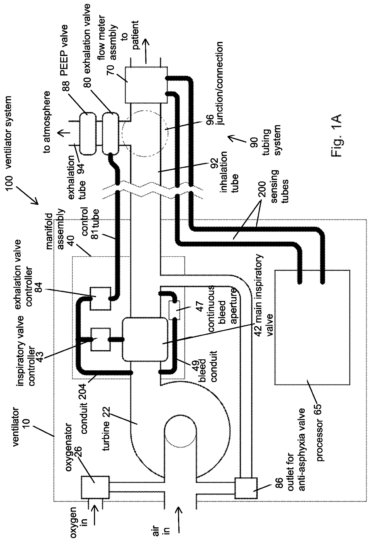
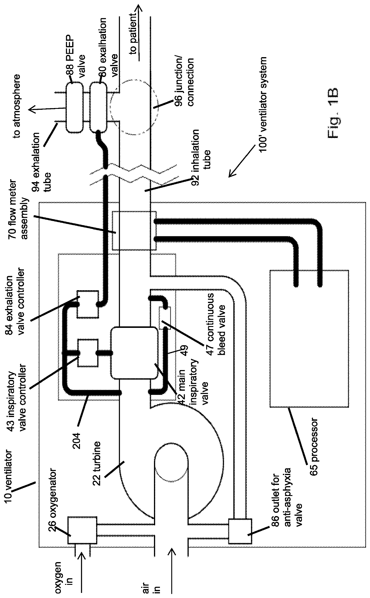
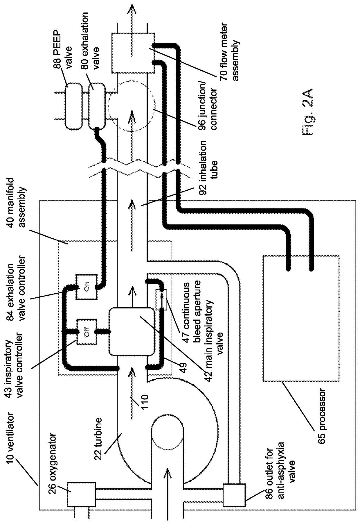
A ventilator system for providing respiratory support in cases of acute respiratory failure or severe trauma is described. The ventilator system has a ventilator and a tubing system. The system is characterized in that the ventilator has a continuous bleed valve configured to be open to air flow from the blower at all times when the blower is operating during both inspiration and expiration; thereby providing a minimal amount of pressure within a patient's lungs at the end of each exhalation—positive end expiratory pressure (PEEP). In an embodiment of the invention the system comprises a manifold block configured to hold the main operating elements of the ventilator.

Description

FIELD OF THE INVENTION[0001]The invention is from the field of medical devices. Specifically the invention is directed to a ventilator system for providing respiratory support in cases of acute respiratory failure or severe trauma.BACKGROUND OF THE INVENTION[0002]Positive pressure ventilators work by forcing air through a drive mechanism, which raises the pressure in the patient's airways relative to atmospheric pressure, which consequently causes the lungs to expand. Currently known ventilators which are suitable for providing such respiratory support are generally large and heavy (on an order of about 3.5-10 kilograms), and may require a separate oxygen cylinder for the pneumatic operation of the device, which adds to the overall transport weight. Moreover, there are many technical problems which must be overcome and for which suitable solutions have not yet been found. For example, it is necessary to provide for a minimal amount of pressure within the patient's lungs at the end o...

Claims


Application Information

Patent Timeline
Patent Type & Authority Patents(United States)
IPC IPC(8): A61M16/00A61M16/08A61M16/20A61M16/10
CPCA61M16/0066A61M16/024A61M16/0816A61M16/0883A61M16/101A61M16/204A61M16/205A61M16/206A61M16/006A61M16/209A61M2016/0021A61M2016/0027A61M2016/0036A61M2205/3306A61M2205/3375A61M2205/50A61M2230/60
Inventor SHAHAR, MARKBARKAI, NIR
Owner INOVYTEC MEDICAL SOLUTIONS
Why Eureka
Try Eureka