Pilot solenoid valve

a solenoid valve and pilot technology, applied in the direction of valve details, valve housings, valve arrangements, etc., can solve the problems that the power saving and minimization of the solenoid valve cannot be expected, and achieve the effect of minimizing the stroke of the plunger

Active Publication Date: 2022-04-19
LIXIL CORP
View PDF102 Cites 0 Cited by
  • Summary
  • Abstract
  • Description
  • Claims
  • Application Information

AI Technical Summary

Benefits of technology

[0012]In some embodiments, provided is a pilot solenoid valve capable of minimizing a stroke of a plunger and miniaturization or power saving of the solenoid valve.

Problems solved by technology

For this reason, since a large electromagnetic force is required, miniaturization and power saving of the solenoid valve cannot be expected.

Method used


Image

  • Pilot solenoid valve
  • Pilot solenoid valve
  • Pilot solenoid valve

Examples


Embodiment Construction

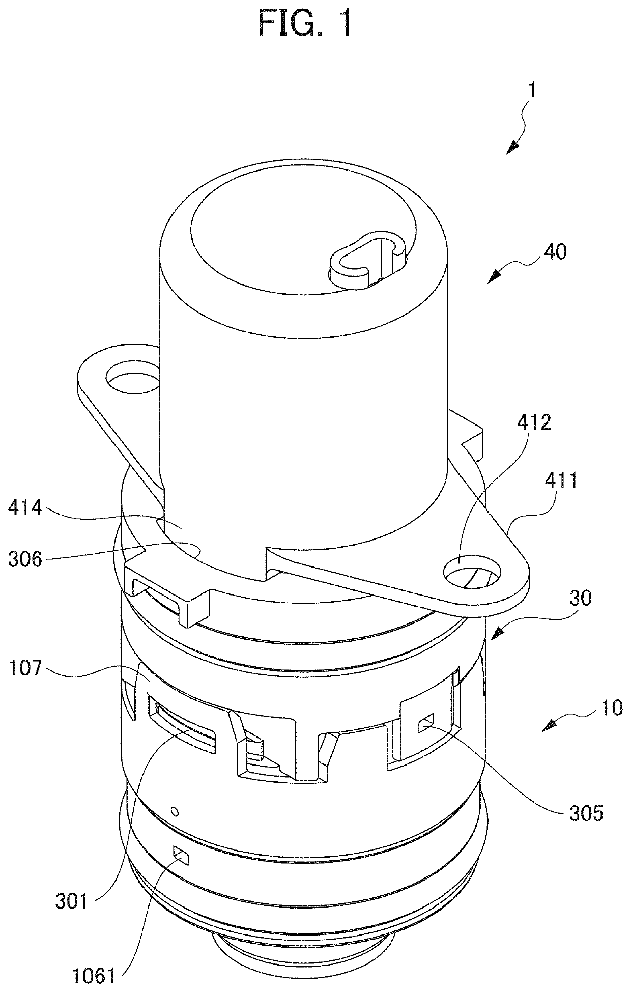
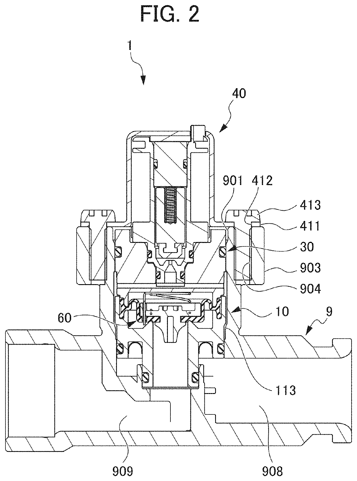
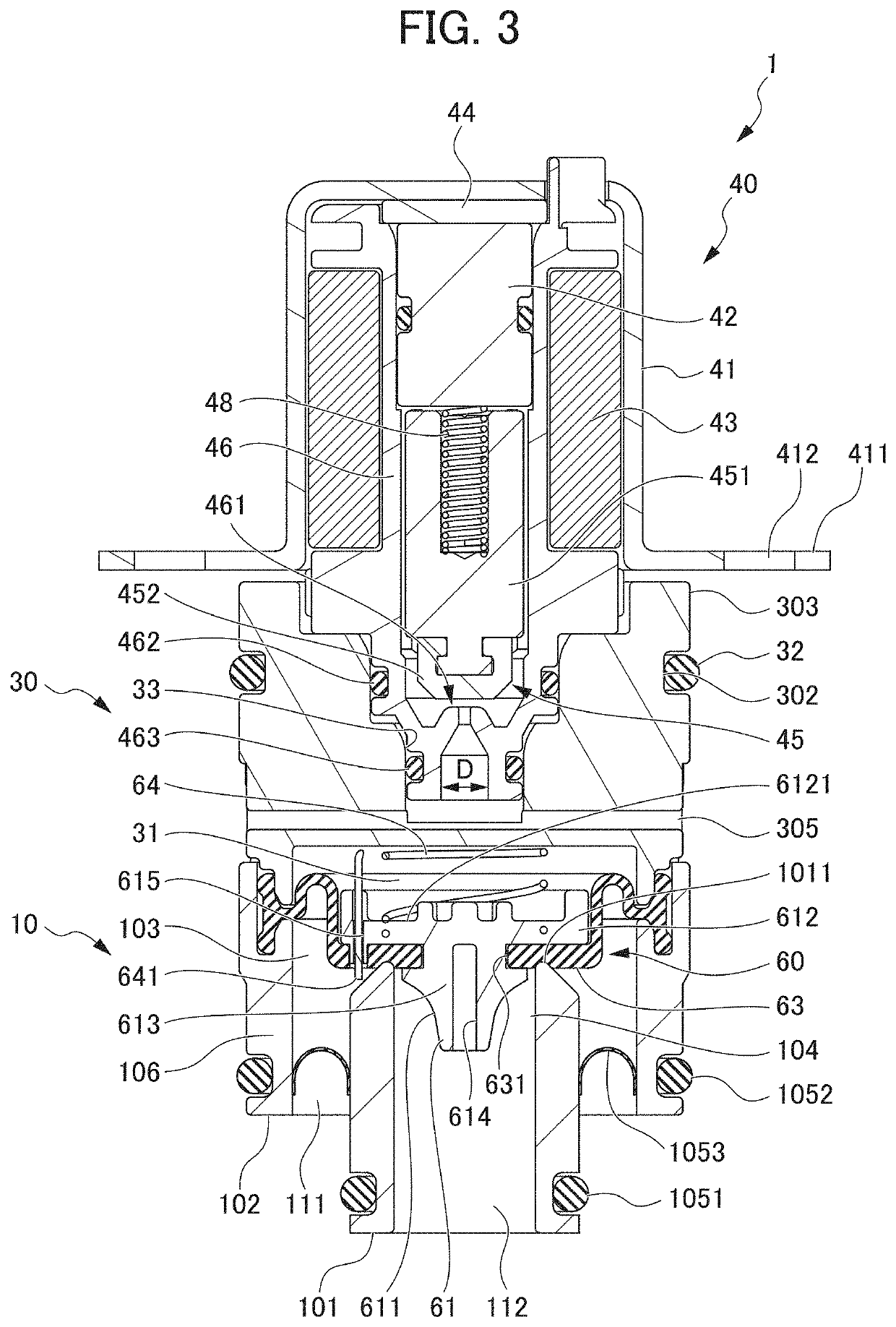
[0023]FIG. 1 is a perspective view illustrating the pilot solenoid valve 1, according to some embodiments. FIG. 2 is a cross-sectional view illustrating a state in which the pilot solenoid valve 1 is attached to a tubular member 9, according to some embodiments. FIG. 3 is a cross-sectional view illustrating the pilot solenoid valve 1, according to some embodiments. FIG. 4 is an exploded perspective view illustrating the pilot solenoid valve 1, according to some embodiments.

[0024]The pilot solenoid valve 1 includes, as illustrated in FIG. 1, a valve base 10, a valve cover 30, and a coil portion 40 and these are connected upward from below in this order as a cartridge type configuration. Namely, the pilot solenoid valve 1 is used while being fixed to the tubular member 9 after the valve base 10 and the valve cover 30 are inserted into an opening portion 901 of the tubular member 9 as illustrated in FIG. 2. The details of fixing the pilot solenoid valve 1 to the tubular member 9 will b...


PUM


Abstract

Provided is a pilot solenoid valve capable of bringing the strokes of a plunger to a necessary minimum and capable of achieving solenoid valve miniaturization and power saving. A pilot solenoid valve is provided with a diaphragm section, a primary side section, a secondary side section, a main valve, a back pressure chamber, a primary side auxiliary flow path, a secondary side auxiliary flow path, an auxiliary valve, and an auxiliary valve drive unit, wherein the secondary side auxiliary flow path is not formed in the main valve but rather is formed in the area around the main valve so as to bypass the main valve.

Description

CROSS-REFERENCE TO RELATED APPLICATIONS[0001]This application is a national stage application under 35 USC 371 of International Application No. PCT / JP2018 / 023230, filed Jun. 19, 2018, which claims the priority of Japanese Application No. 2017-124228, filed Jun. 26, 2017, and Japanese Application No. 2018-061945, filed Mar. 28, 2018, the entire contents of each of which are incorporated herein by reference.FIELD OF THE DISCLOSURE[0002]The present invention relates to a pilot solenoid valve.BACKGROUND OF THE DISCLOSURE[0003]In the related art, it has been known that a solenoid valve is provided in a flow path of a liquid and the opening and closing of the solenoid valve is controlled so as to control the flow of the liquid. One example of a solenoid valve is a pilot solenoid valve. The pilot solenoid valve includes, for example, a diaphragm, and in the pilot solenoid valve, an opening of an end portion of an auxiliary flow path is formed at an upper end of a diaphragm portion, and if ...

Claims


Application Information

Patent Timeline
Patent Type & Authority Patents(United States)
IPC IPC(8): F16K31/06F16K31/40F16K1/42F16K27/00F16K27/02F16K31/42
CPCF16K31/0655F16K1/42F16K27/00F16K27/02F16K31/404F16K31/0675F16K31/406F16K31/42F16K31/06F16K31/40
Inventor DOMOTO, NAOKISAKATA, SHINYA
Owner LIXIL CORP
Why Eureka
Try Eureka