Fast-acting fluid control valve

a fluid control valve and fast-acting technology, applied in the direction of valve operating means/release devices, pressure relieving devices on sealing faces, transportation and packaging, etc., can solve the problem of limited speed, achieve faster opening and closing, reduce moving mass, and reduce the effect of moving distan

Inactive Publication Date: 2010-05-18
PURDUE RES FOUND INC
View PDF18 Cites 4 Cited by
  • Summary
  • Abstract
  • Description
  • Claims
  • Application Information

AI Technical Summary

Benefits of technology

[0006]The present invention provides a fast-acting fluid control valve capable of opening and closing more rapidly than existing valves of comparable size (flow area) because of a reduced moving mass, decreased moving distance, and increased actuator properties.
[0007]The fluid control valve includes an annular-shaped spool and a housing having an annular-shaped spool cavity in which the spool is received so as to be capable of axial movement within the spool cavity between first and second spool positions. The spool has multiple radial passages therethrough and multiple axially-spaced circumferential spool sealing features. The housing has multiple axially-spaced circumferential housing sealing features configured and disposed within the spool cavity so that, with the spool in the first spool position, fluid flow is enabled through the spool cavity, the fluid flow being enabled radially through the radial passages of the spool and axially between the circumferential spool sealing features and the circumferential housing sealing features. With the spool in the second spool position, the circumferential spool sealing features and the circumferential housing sealing features cooperate to substantially prevent fluid flow through the spool cavity.
[0009]According to another preferred aspect of the invention, the fluid control valve is capable of opening and closing much faster than conventional valves of equivalent size (flow area) due to employing a spool of minimal mass and minimal stroke. The mass of the spool can be minimized as a result of being annular shaped with minimal wall thickness, made possible because the spool has equal and opposite flow paths (and hence pressure) on its interior and exterior that cancel out radial stresses (hoop stresses). The spool provides multiple flow paths along its length, both circumferentially around its inner and outer surfaces as well as radially through the wall of the spool, and is capable of maximizing flow area per displacement so that the stroke of the spool can be minimized. Additional flow paths can be provided by including paths in the axial direction of the spool.
[0010]The minimal mass of the spool reduces the power required to move it, allowing for the use of a variety of actuators to stroke the spool. Preferred actuators are electromagnets having rapid response times and decreased mass, made possible in part as a result of the annular shape of the spool. For example, lag time for activation can be minimized because very thin annular-shaped electromagnets can be used with the annular-shaped spool, and eddy currents are able to more rapidly decay within an annular-shaped electromagnet.
[0011]The spool can be configured to have contact sealing surfaces or viscous sealing surfaces, with the former being preferred to minimize manufacturing costs and promote durability and reliability, such as resistance to wear and contamination. Multiple contact sealing surfaces can be achieved by manufacturing the spool in segments and assembling the segments within the spool housing, or configuring a one-piece spool to have minimal overlaps at the contact sealing surfaces and using thermal expansion and / or mechanical elastic stretching of spool and / or housing to assemble the spool.

Problems solved by technology

While the spool is capable of rapidly opening and closing in part due to the very small size of the spool, speed is limited by inherent eddy currents in the spool and the relatively large mass of the spool resulting from its relatively thick wall.
Nonetheless, the spool is a check valve that cannot open against very high pressures because it is not axially balanced.

Method used


Image

  • Fast-acting fluid control valve
  • Fast-acting fluid control valve
  • Fast-acting fluid control valve

Examples


Embodiment Construction

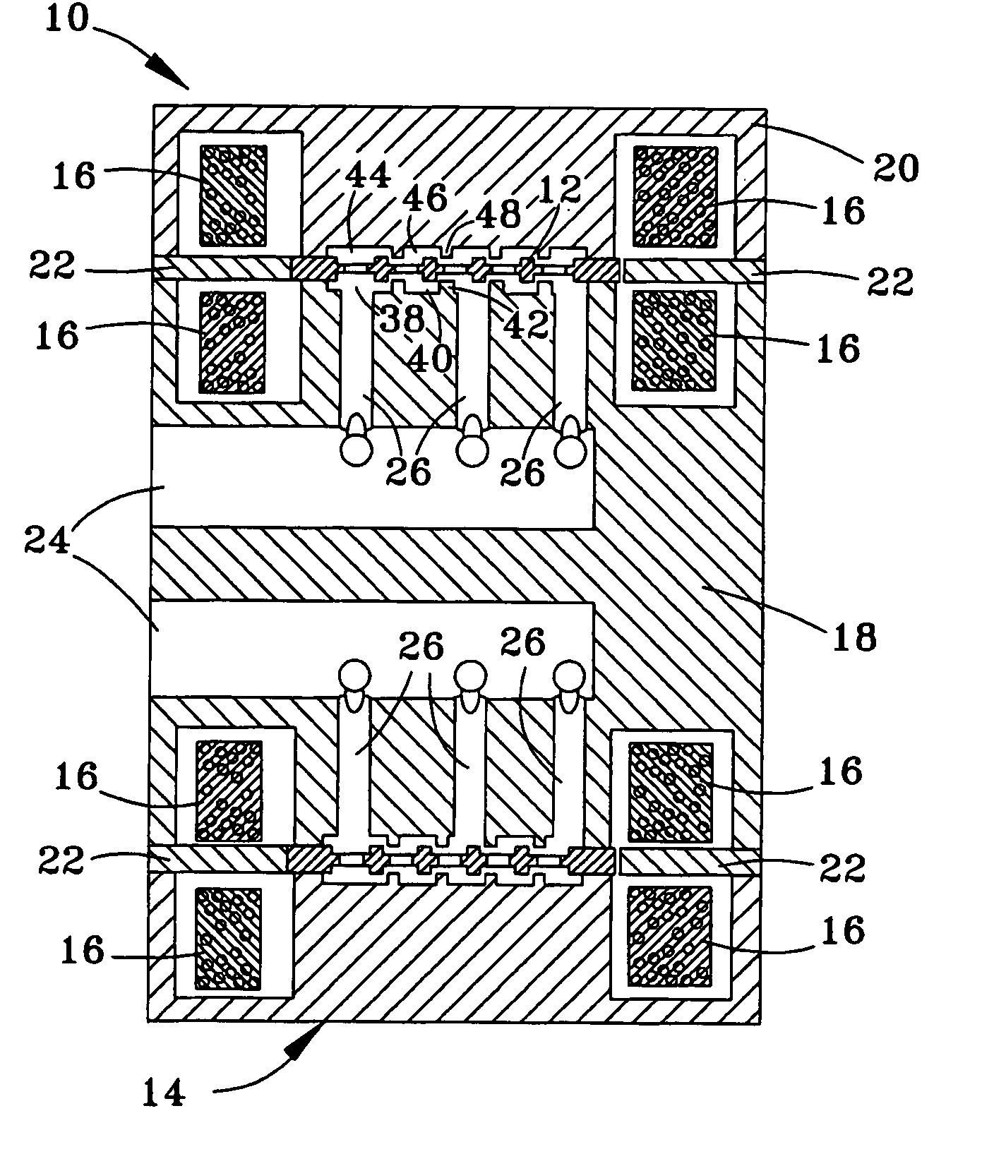
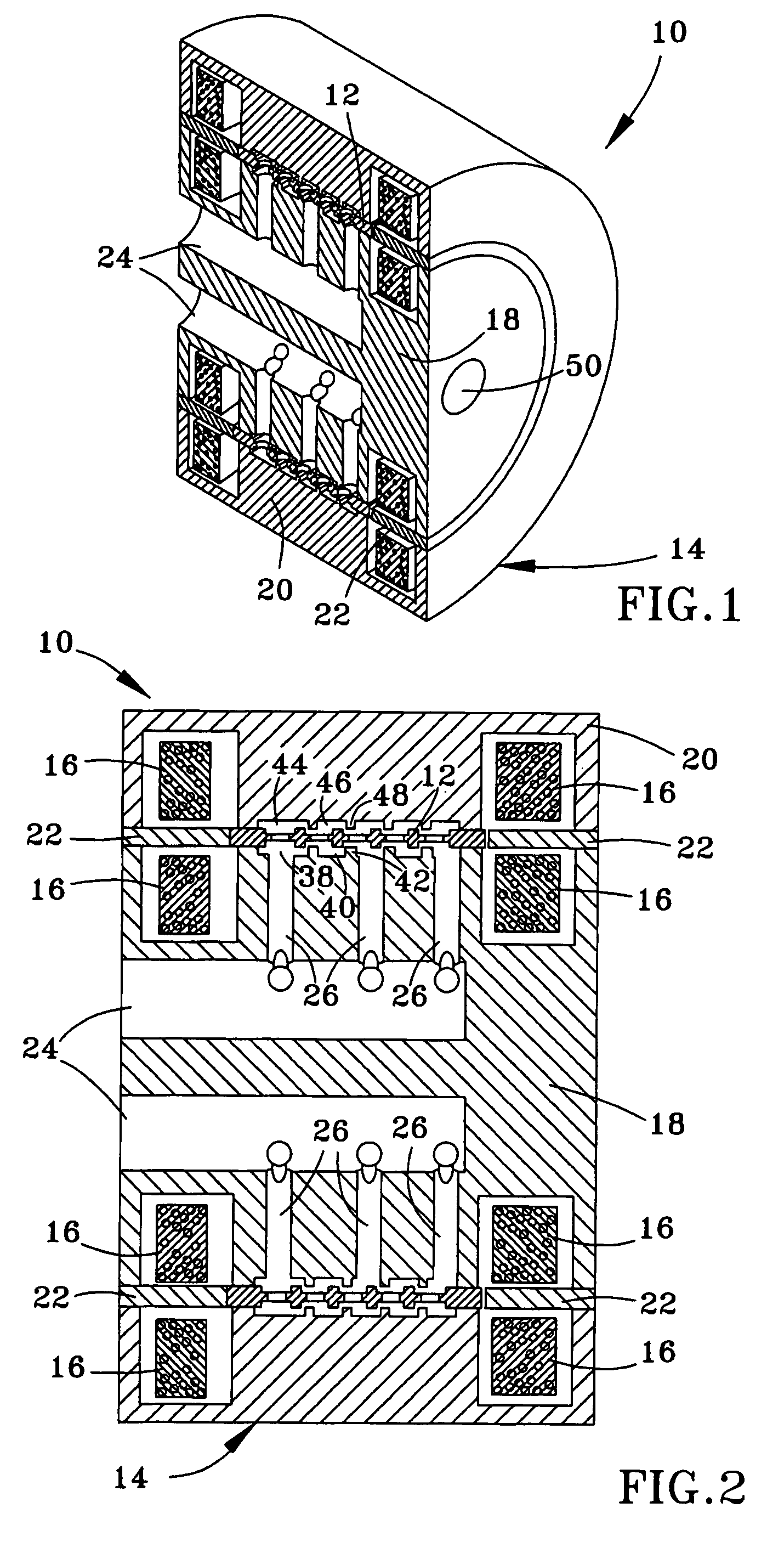
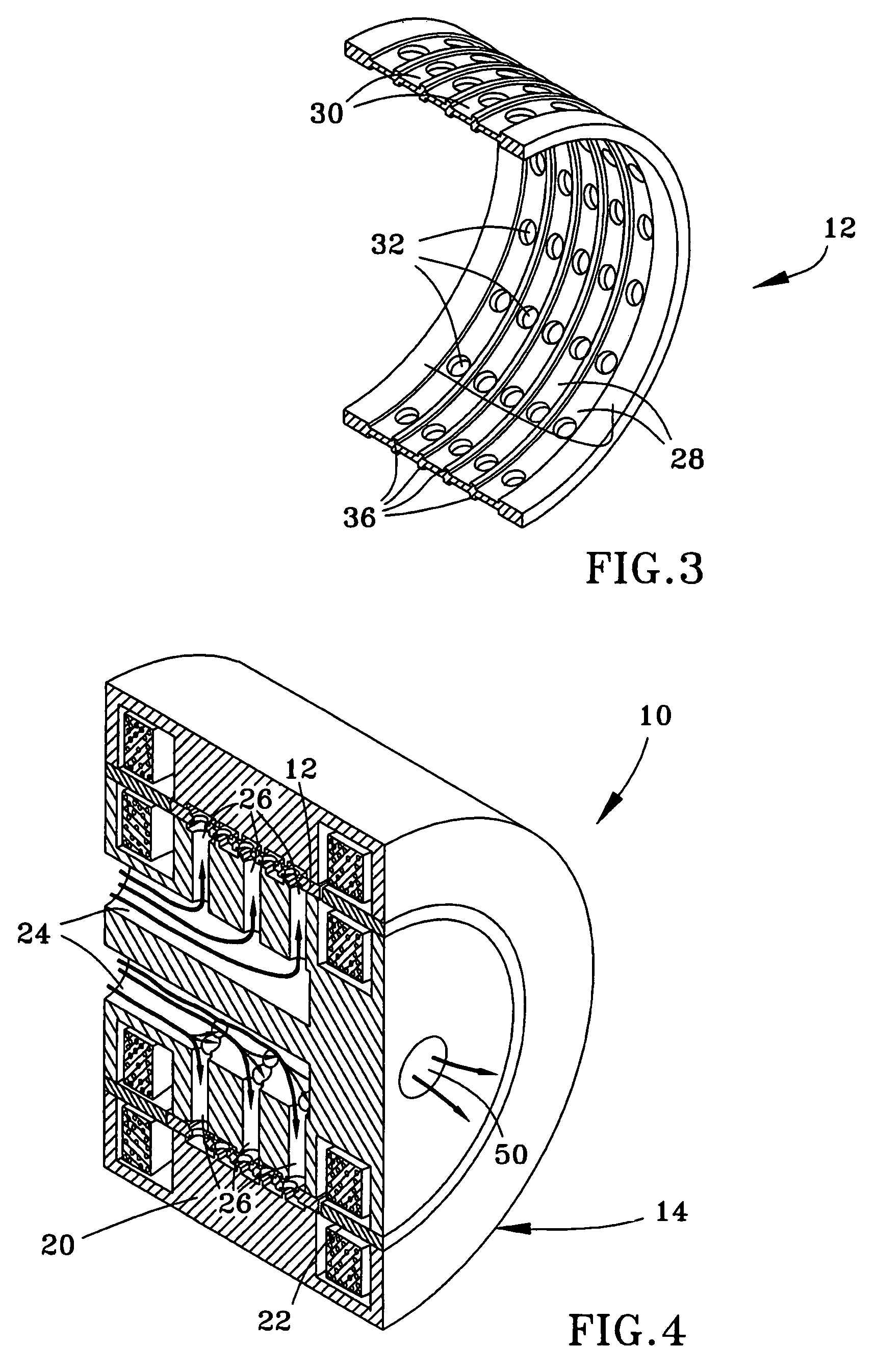
[0026]FIGS. 1 through 18 illustrate several embodiments of valve assemblies configured in accordance with the present invention. It should be noted that the Figures are drawn for purposes of clarity when viewed in combination with the following description, and therefore are not necessarily to scale.

[0027]An original and general goal for valve assemblies of this invention is to exhibit a pressure drop of about 1 bar at flow rates of about 10 liters per minute (lpm), and the ability go from a fully closed to a fully open position, and vice versa, in about 0.5 milliseconds (ms) or less. Further goals were for valve assemblies that are suitable for high volume manufacturing, consume little energy, and are reliable for millions of cycles. While such goals are intended, valve assemblies that do not meet these goals but otherwise incorporate key design feature of this invention are also within the scope of the invention.

[0028]Basic components of valve assemblies of this invention include ...


PUM


Abstract

A fluid control valve capable of rapidly opening and closing. The valve includes a housing with an annular-shaped spool cavity that contains an annular-shaped spool capable of axial movement within the spool cavity between first and second spool positions. The spool has axially-spaced circumferential spool sealing features and optionally radial passages therethrough. The housing has axially-spaced circumferential housing sealing features configured and disposed within the spool cavity so that, with the spool in the first spool position, fluid flow is enabled through the spool cavity axially between the spool sealing features and the housing sealing features, which provide axial force balancing of the spool. With the spool in the second spool position, the spool sealing features and the housing sealing features cooperate to substantially prevent fluid flow through the spool cavity.

Description

CROSS REFERENCE TO RELATED APPLICATIONS[0001]This application claims the benefit of U.S. Provisional Application No. 60 / 747,427, filed May 17, 2006, the contents of which are incorporated herein by reference.BACKGROUND OF THE INVENTION[0002]The present invention generally relates to fluid control valves. More particularly, this invention relates to a fast-acting fluid control valve capable of opening and closing more quickly that conventional valves of comparable flow capacity as a result of reduced moving mass, decreased stroke distance, and increased actuator properties, which preferably include reduced magnetic diffusion time (less lag before activation / deactivation) and increased force to mass ratio.[0003]Research efforts have been made to design fluid control valves with rapid opening and closing speeds. Examples include U.S. Pat. Nos. 6,105,616 and 6,474,353 to Sturman et al., which disclose a valve with two connected flow paths defined at the outer circumferential surface of ...

Claims


Application Information

Patent Timeline
Patent Type & Authority Patents(United States)
IPC IPC(8): F16K11/07
CPCF16K31/0675F16K11/0716Y10T137/86759
Inventor BATDORFF, MARK A.LUMKES, JR., JOHN H.
Owner PURDUE RES FOUND INC
Why Eureka
Try Eureka