Collated rebar clinch clip

a technology of collapsing rebar and clinch, which is applied in the field of collapsing rebar clinch clips, can solve the problems of poor tension, costly and backbreaking operation, and the manufacture of such clips does not lend itself to efficient configuration, so as to achieve tight connection, less cost, and tighter connection

Active Publication Date: 2022-05-03
AYRES DON
View PDF69 Cites 1 Cited by
  • Summary
  • Abstract
  • Description
  • Claims
  • Application Information

AI Technical Summary

Benefits of technology

[0007]In accordance with the invention, many of the problems associated with time-consuming, backbreaking labor while tying rebar together are avoided by providing collated rebar clinch clips and a crimping tool with a magazine to hold the clips.
[0008]The devices disclosed herein provide an effective means for tying lengths of rebar together that is quicker, less costly, and makes for a tighter connection.
[0014]A feature of the invention is that the actuator includes a handle spaced from the blade and anvil such that a worker may operate the tool standing upright without bending over when the intersecting rebar to be joined is located at the worker's feet.

Problems solved by technology

It is very strong in compression, but it is weak in tension as the concrete holding the aggregate together can crack allowing the structure to fail.
This is typically done manually and is a costly and backbreaking operation.
While integrally-formed, H-shaped clips that may be used to tie the rebar together could be punched out of thin, flat stock material, the manufacture of such clips does not lend itself to efficient configurations and would create significant amounts of waste.

Method used


Image

  • Collated rebar clinch clip
  • Collated rebar clinch clip
  • Collated rebar clinch clip

Examples


first embodiment

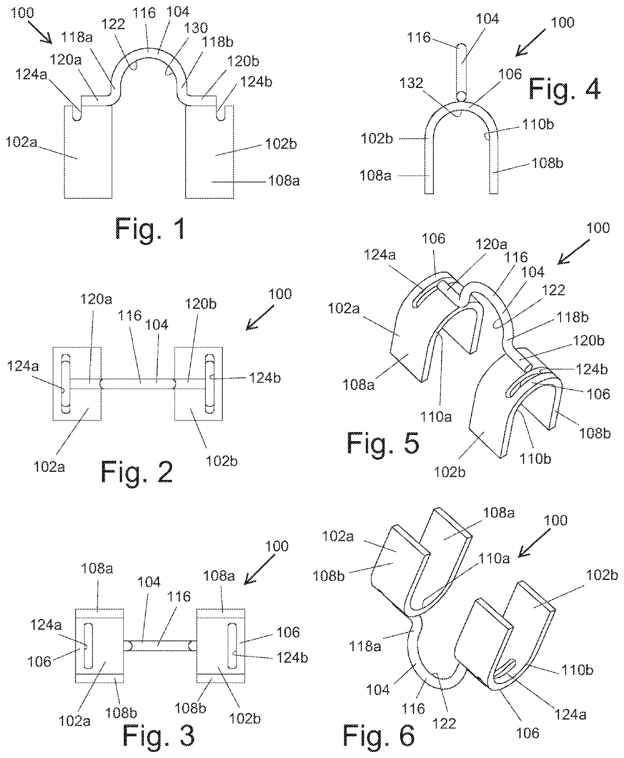
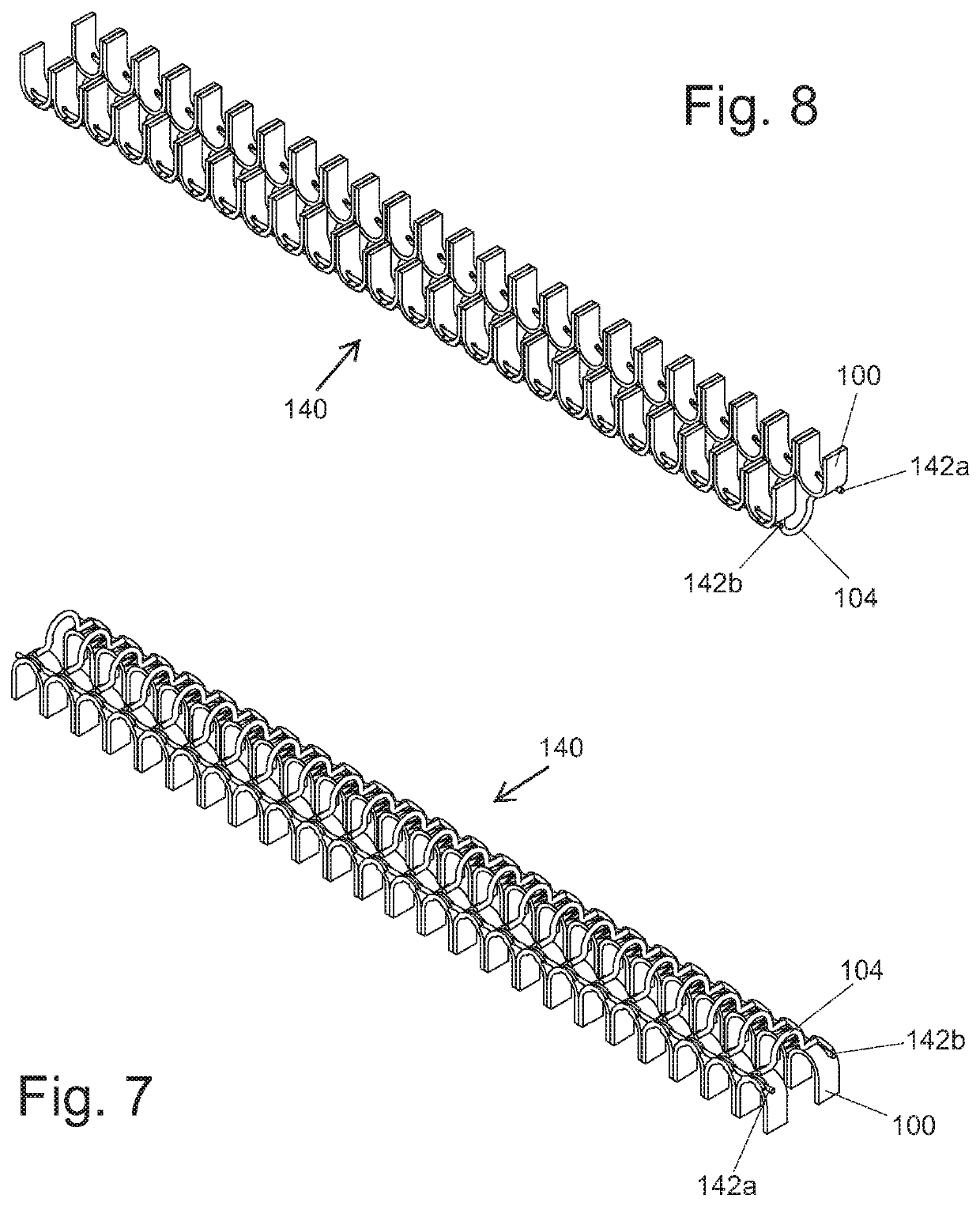
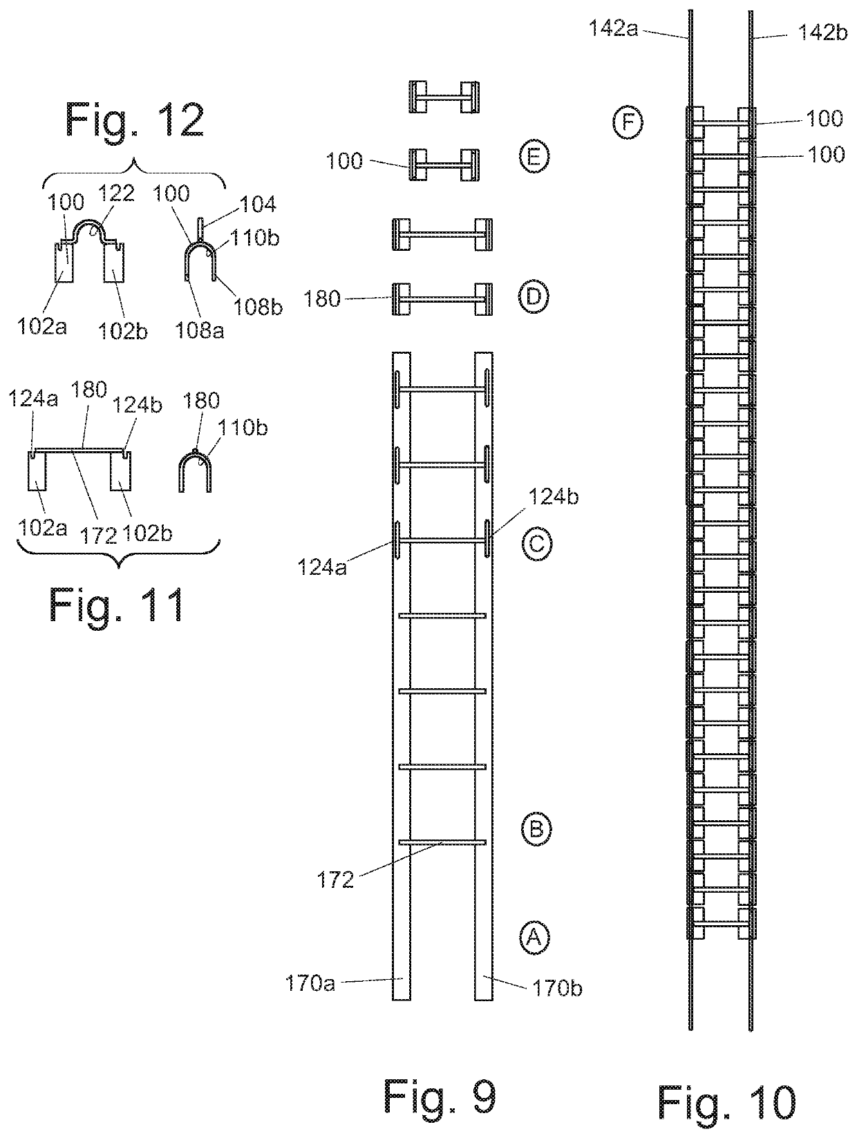
[0064]In FIGS. 1-18, a collated rebar clinch clip, generally designated 100, for fixing two lengths of rebar together is shown. As best seen in FIGS. 13-18, the clip 100 is positioned over two lengths rebar, a longitudinally-extending upper rebar 150 and an underlying laterally-extending lower rebar 152 orthogonal to and abutting the bottom of the upper rebar 150.

[0065]As seen in FIGS. 1-6, an individual clip 100, which may be made of low carbon steel, has three components, namely, a pair of crimp elements 102a,102b and an arched bridge element 104, connecting the crimp elements 102a,102b that are located below in laterally spaced relation.

[0066]Each of the crimp elements 102a,102b is a U-shaped strip having a center bight portion 106 and a pair of parallel downwardly-extending legs 108a,108b. The legs 108a,108b of the crimp elements 102a,102b define a pair of aligned, laterally-extending openings 110a,110b through which the lower rebar 152 extends. The bight portions 106 of the cri...

second embodiment

[0075]FIGS. 19-21 show a rebar clinch clip prior to forming. The clip, generally designated 200, has three components, namely, a pair of crimp elements 202a,202b and a bridge element 204 connecting the crimp elements 202a,202b that are located in laterally spaced relation. The crimp elements 202a,202b and the bridge element 204 are formed from metal, such as steel, and have a rectangular cross-section.

[0076]Each of the crimp elements 202a,202b is a strip having a center portion 206 and a pair of legs 208a,208b extending outwardly therefrom. The legs 208a,208b of the crimp elements 202a,202b when formed define a pair of aligned, laterally-extending openings through which the lower rebar 152 will extend. Formed in the center portion 206 of each crimp element 202a,202b is a pair of spaced, upright prongs 212a,212b space inward from one edge and slots 224a,224b intermediate the prongs 212a,212b and the opposite edge.

[0077]The bridge element 204 is a bar having a center portion 216 and a...

third embodiment

[0079]FIG. 22 shows a rebar clinch clip prior to shaping of the clip elements into U-shaped forms. The clip, generally designated 300, has three components, namely, a pair of crimp elements 302a,302b and a bridge element 304 connecting the crimp elements 302a,302b that are located in laterally spaced relation. The crimp elements 302a,302b and the bridge element 304 are formed from metal, such as steel, and have a rectangular cross-section.

[0080]Each of the crimp elements 302a,302b is a strip having a center portion 306 and a pair of legs 308a,308b extending outwardly therefrom. The legs 308a,308b of the crimp elements 302a,302b when formed define a pair of aligned, laterally-extending openings through which the lower rebar 152 will extend. Formed in the center portion 306 of each crimp element 302a,302b is a pair of spaced prongs 312a,312b spaced inward from one edge and a slot 324 intermediate the prongs 312a,312b and the opposite edge.

[0081]The bridge element 304 is a bar having a...


PUM


Abstract

A collated rebar clinch clip has three components including a pair of spaced U-shaped crimp elements and a U-shaped bridge element connecting the crimp elements. The crimp elements and bridge element are cut from continuous lengths of stock material. A plurality of clinch clips are joined together by a pair of cords to form a collated series of clinch clips that may be arranged in a linear series or spirally wound to form a coil. The tool includes a frame, a die set with a sliding blade and a fixed anvil, an actuator to linearly move the blade relative to the anvil, and a magazine to hold collated clinch clips for sequential delivery between the blade and anvil to tie together a first length of rebar extending through the bridge element and a second orthogonal length of rebar extending through the crimp elements.

Description

CROSS-REFERENCE TO RELATED APPLICATIONS[0001]This application claims the benefit under 35 U.S.C. § 119(e) of U.S. Provisional Patent Application Ser. No. 63 / 020,536, filed May 5, 2020, the entire contents of which are incorporated herein by reference.BACKGROUND OF THE INVENTIONTechnical Field[0002]The present invention relates to clips and, more particularly, to collated rebar clinch clips used for tying rebar together.Background Art[0003]Concrete is a composite material made of fine and coarse aggregate bonded together with a fluid cement. After being poured and over time, it hardens and cures into a stone-like substance.[0004]Concrete is a convenient material used to construct roads, buildings, and other manmade structures. It is very strong in compression, but it is weak in tension as the concrete holding the aggregate together can crack allowing the structure to fail. To prevent this, steel reinforcing bars, or rebar, is placed within the concrete during construction to add tens...

Claims


Application Information

Patent Timeline
Patent Type & Authority Patents(United States)
IPC IPC(8): E04C5/16E04G21/12
CPCE04C5/167E04G21/122
Inventor AYRES, DON
Owner AYRES DON
Why Eureka
Try Eureka