
Method and device for transmitting or receiving data in wireless communication system

a wireless communication system and wireless communication technology, applied in the direction of digital transmission, electrical equipment, synchronisation arrangement, etc., can solve the problem of needing more advanced mobile communication systems, and achieve the effect of preventing a signalling overhead

Active Publication Date: 2022-05-17
LG ELECTRONICS INC
View PDF9 Cites 1 Cited by
  • Summary
  • Abstract
  • Description
  • Claims
  • Application Information

AI Technical Summary

Benefits of technology

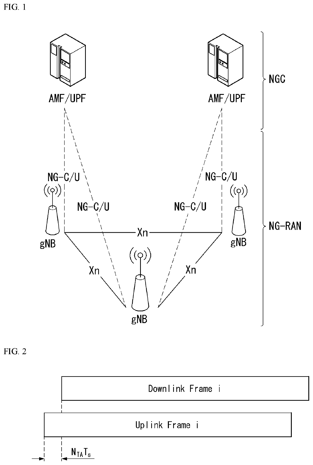
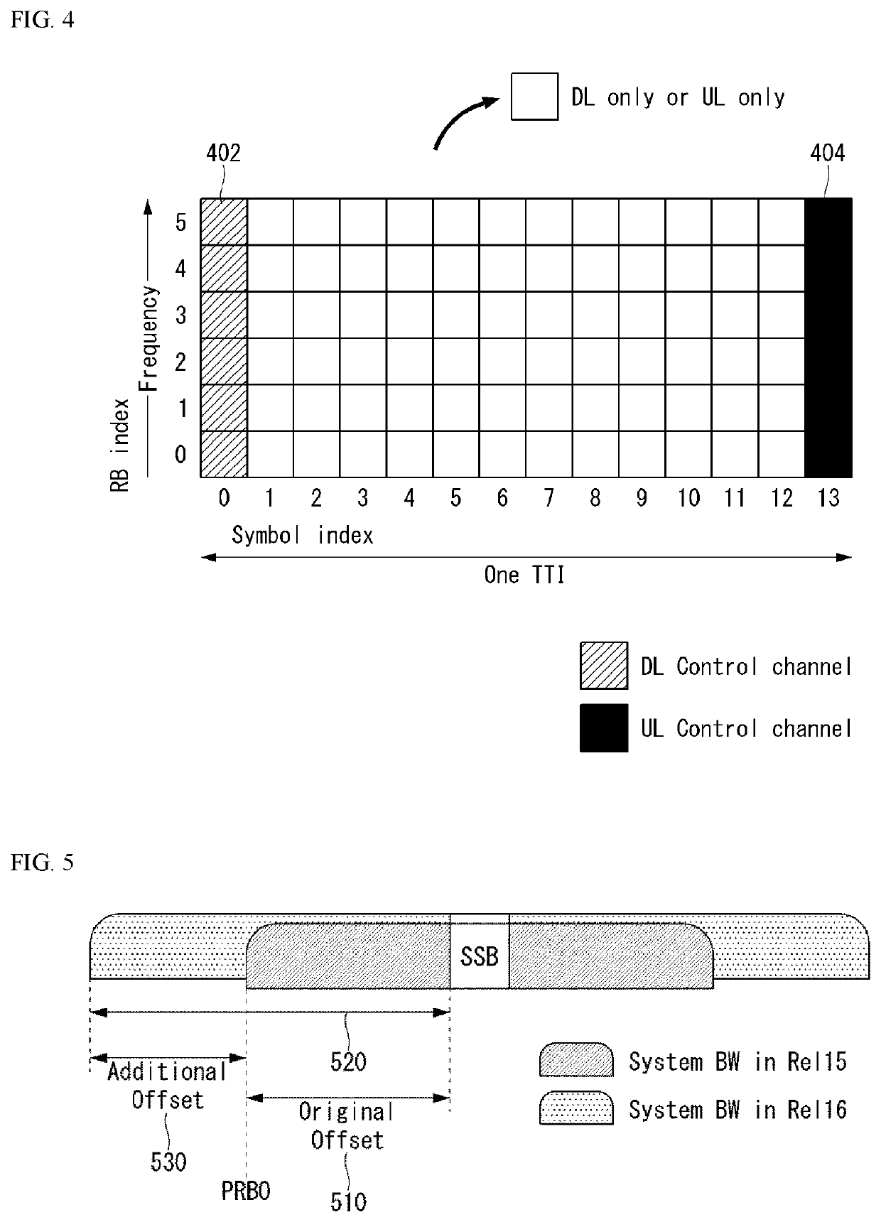
[0019]The present disclosure has an effect of capable of forming a common PRB grid by providing additional offset information for determining a reference point when a system bandwidth increases due to an increase in a performance of a system.
[0020]The present disclosure has an effect of capable of preventing a signalling overhead by using information of PRB0 corresponding to a common reference point for each numerology.

Problems solved by technology

However, as current mobile communication systems suffer resource shortages and users demand even higher-speed services, development of more advanced mobile communication systems is needed.

Method used


Image

  • Method and device for transmitting or receiving data in wireless communication system
  • Method and device for transmitting or receiving data in wireless communication system
  • Method and device for transmitting or receiving data in wireless communication system

Examples


first embodiment

[0118]A first embodiment relates to common PRB indexing for bandwidth part (BWP) configuration.

[0119]In a NR system, the common PRB indexing may be used for a base station to configure a bandwidth part (BWP) to a UE or configure a RS sequence to the UE.

[0120]However, as a bandwidth of a communication system increases, a size of the above-described offset increases. Therefore, all the offset cannot be represented by 9 bits.

[0121]A plurality of methods for solving the problem is described below.

[0122](Method 1)

[0123]In a wideband, multiple SS blocks may exist, and the SS block may be additionally configured as a performance of the system is improved (or as a system bandwidth increases).

[0124]In this instance, a release-15 UE may be configured not to access the network in the added SS block in order to maintain existing common PRB indexing.

[0125]This can be performed by different sync raster configurations or the use of a new sync sequence.

[0126]When the release-15 UE is allowed to be ...

second embodiment

[0180]A second embodiment relates to a method of indicating a common offset for different numerologies.

[0181]A NR system may support various numerologies, and a UE accessing the NR system may use common PRB indexing corresponding to each numerology.

[0182]That is, it is assumed that the UE receives an indication for a reference point from the network and then is configured with a bandwidth part from the network.

[0183]In this instance, if the configured bandwidth part has subcarrier spacing attributes of 15 kHz, the UE checks a location of the bandwidth part configured with the common PRB indexing formed using 15 kHz subcarrier spacing.

[0184]Alternatively, if the configured bandwidth part has subcarrier spacing attributes of 30 kHz, the UE checks a location of the bandwidth part configured with the common PRB indexing formed using 30 kHz subcarrier spacing.

[0185]In order to use the common PRB indexing, the UE receives, from the network, an offset value from the SS block accessing the ...


PUM


Abstract

The present disclosure provides a method for transmitting and receiving data based on a grid of a common resource block (RB) in a wireless communication system. More specifically, the method performed by a user equipment includes receiving a synchronization block from a base station; receiving, from the base station, first offset information representing an offset between a lowest subcarrier of a lowest resource block of the SSB and a first reference point based on a specific subcarrier spacing; receiving, from the base station, control information including information on the specific subcarrier spacing and information on a difference between a subcarrier spacing based reference point, to which the SSB is received, and the first reference point; and configuring a grid of a common resource block based on the first offset information and the control information.

Description

CROSS-REFERENCE TO RELATED APPLICATIONS[0001]This application is a National Stage filing under 35 U.S.C. 371 of International Application No. PCT / KR2018 / 011699, filed on Oct. 2, 2018, which claims the benefit of U.S. Provisional Application No. 62 / 567,208, filed on Oct. 2, 2017, the contents of which are all hereby incorporated by reference herein in their entirety.TECHNICAL FIELD[0002]The present disclosure relates to a wireless communication system, and more particularly to a method for transmitting and receiving data and a device supporting the same.BACKGROUND ART[0003]Mobile communication systems have been generally developed to provide voice services while guaranteeing user mobility. Such mobile communication systems have gradually expanded their coverage from voice services through data services up to high-speed data services. However, as current mobile communication systems suffer resource shortages and users demand even higher-speed services, development of more advanced mob...

Claims


Application Information

Patent Timeline
Patent Type & Authority Patents(United States)
IPC IPC(8): H04W56/00H04W72/04H04L5/00
CPCH04W56/001H04L5/001H04W72/04H04L5/00H04W56/00
Inventor SONG, HUAYUEYI, YUNJUNG
Owner LG ELECTRONICS INC
Learn More