Bistatic radar system for motor vehicle applications

a radar system and motor vehicle technology, applied in the field of bistatic radar systems, can solve the problems of inability to accurately estimate the target radar cross-section, inability to accurately inability to detect the target radar, etc., to achieve the effect of reducing cable/wiring costs and improving target radar cross-section estimation

Active Publication Date: 2022-06-21
MOBILE TECH SOLUTIONS LLC
View PDF8 Cites 1 Cited by
  • Summary
  • Abstract
  • Description
  • Claims
  • Application Information

AI Technical Summary

Benefits of technology

[0006]An improved bistatic radar system for all-around pre-crash detection and short-range driver assistance (1) reduces cable / wiring costs, (2) improves target radar cross-section estimation, and (3) provides rapid reconfiguration to adapt to the driving scenario.
[0008]Because each radar module contains all of the hardware to operate as receiver or transmitter, the computing power to perform either the receive function or the transmit function, and the target tracking algorithm processing, the module may be dynamically configured to switch between these roles. This allows the module to dynamically change the transmitter-receiver pairing for improved coverage around the vehicle.
[0011]The cabling requirement for the disclosed radar systems can provide an improvement over known bistatic radar systems. The star-like twisted-pair configuration can be replaced with a more ring-like configuration because each module contains the distributed processing capability to run the target range estimation and target tracking algorithm within the radar module when it is configured as the receiver. The cabling requirement is reduced by approximately half compared to known bistatic radar systems. In another embodiment of the invention, the twisted-pair synchronization ring is replaced by an inductively switched single-wire current loop for timing synchronization. A small current is pulled from a voltage source and drawn around the current loop through an inductor and resistor to a sink. Quickly disabling the source and sink creates a fast voltage swing which is sensed at each module to create a timing synchronization signal.
[0012]In other embodiments, the high-speed differential pair wiring around the ring is also eliminated to further reduce the cabling costs by accomplishing timing synchronization through alternative means. When using these alternative means, each module need only connect to the low-latency bus ringed around to each module and to a central coordinating processor which interfaces to the rest of the automobile's safety system. The alternative synchronization methods are possible by taking advantage of the divider circuits within the PLL of each module. The PLL divider becomes part of a counter circuit that is used for timing synchronization, providing timing resolution under 200 pico-seconds. The reference signal for synchronization may be provided periodically over the low-speed bus by one of the modules tasked to provide the synchronization signal or from the centralized safety system processor of the vehicle. The actual counter value reached between successive synchronization signals is compared to the expected counter value, assuming the targeted VCO frequency, and used to adjust the expected counter value used to schedule future transmit pulse events or to begin integration in the bi-static range time-of-flight measurements in the receiver.
[0013]In still another embodiment, a pair of modules may synchronize directly from the transmitter radar pulse. In this implementation, the transmitter schedules pulses at a specified repetition rate. Forewarned of the approximate transmit timing, the receiver module configures gain and threshold settings to detect the direct path radar signal between transmitter and receiver. The counter from the PLL divider is then triggered by successive receiver comparator threshold exceedances to compare the actual counter value to the expected counter value. The error value is then used to adjust the scheduled counter value that begins integration in the bi-static range time-of-flight measurements for the reception of the next scheduled transmit pulse signal. This implementation improves upon previous art by using the methodology previously used for bi-static range zeroing and using it for timing synchronization as well, thereby eliminating the need for the high-speed synchronization bus.

Problems solved by technology

While passive restraints unquestionably save lives and reduce injuries, the speed at which airbags deploy can cause severe injuries such as whiplash, traumatic brain injuries, and neck and spine injuries.
This technique has undesirable accuracy limitations when the amplitude of the radar signal leaking straight from the transmit antenna to the receive antenna is not well characterized.

Method used


Image

  • Bistatic radar system for motor vehicle applications
  • Bistatic radar system for motor vehicle applications
  • Bistatic radar system for motor vehicle applications

Examples


Embodiment Construction

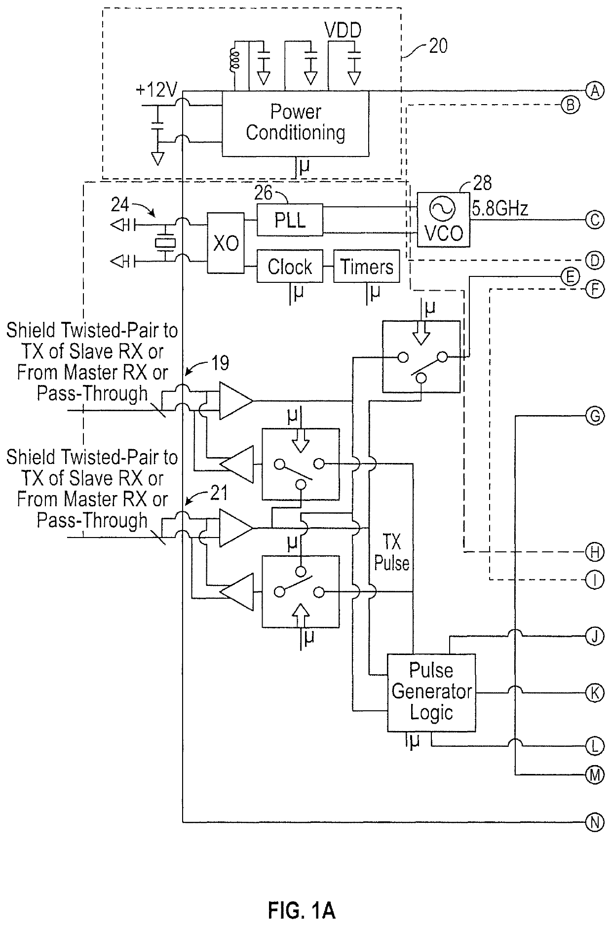
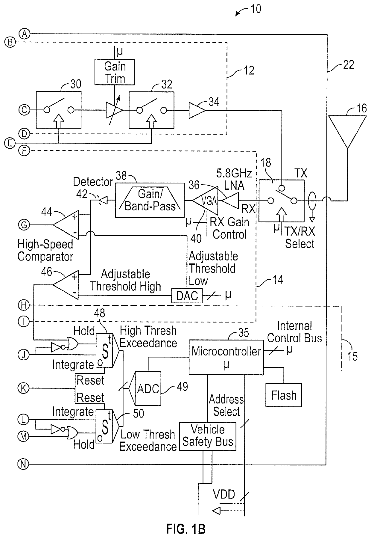
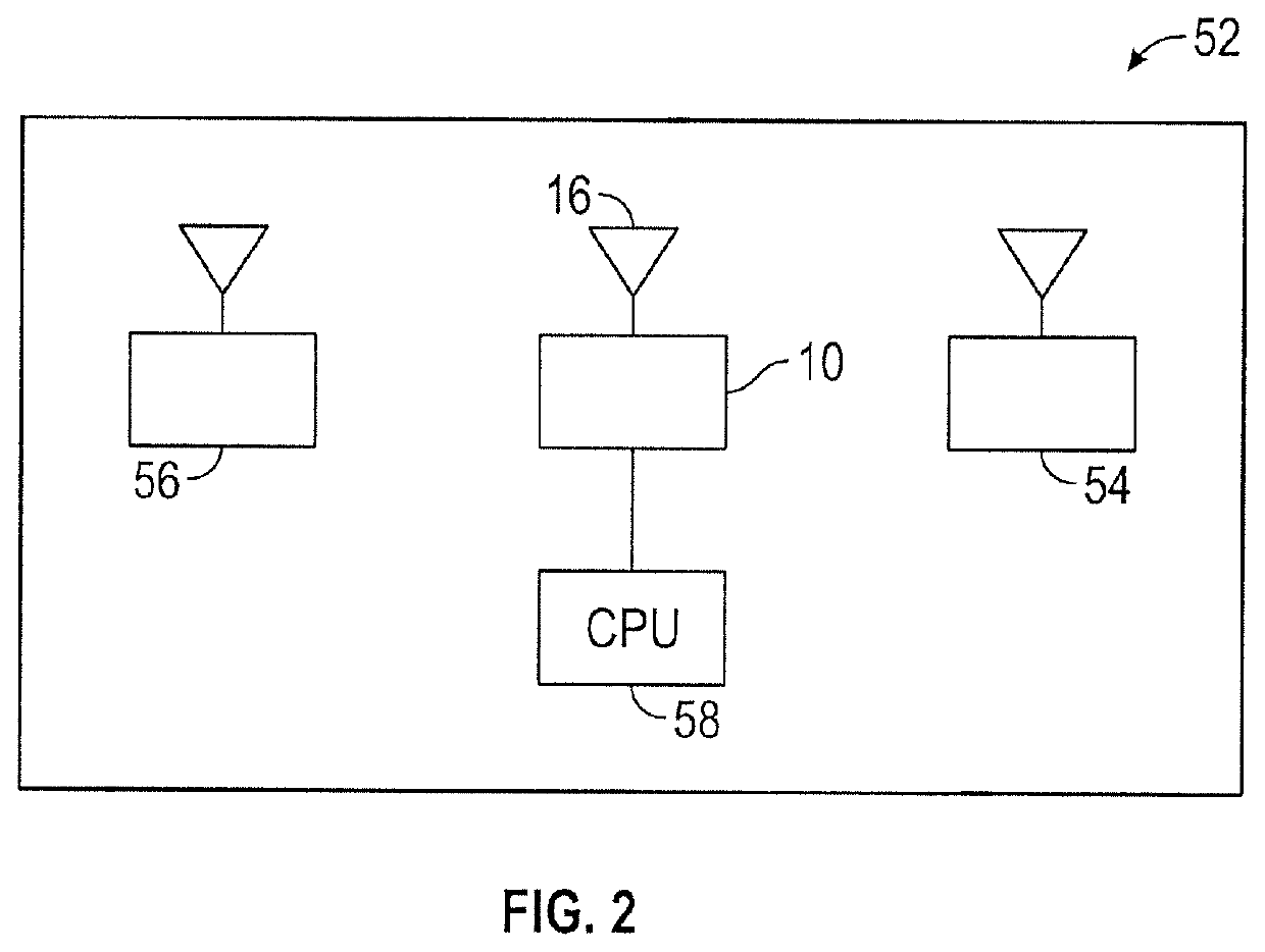
[0022]Shown in FIGS. 1A and 1B are a schematic illustration of a radar module 10 having transmitter circuitry 12, receiver circuitry 14, and a timing and control section 15. Module 10 has an associated antenna 16 that acts as a transmitter antenna for circuitry 12 and as a receiver antenna for circuitry 14, depending on the state of switch 18. Module 10 may include a power conditioning section 20, such as to regulate voltage and improve power quality to enable load equipment to function properly. The term “module” as used herein refers to the combination of a timing and control section 15, transmitter circuitry 12, and receiver circuitry 14 sharing a single antenna 16, and / or to a combination in which the timing and control section 15, transmitter circuitry 12, and receiver circuitry 14 are on the same printed circuit board 22.

[0023]Transmitter circuitry 12 includes a voltage-controlled oscillator (VCO) 28. The VCO is tuned using the timing reference crystal 24 and a phase locked lo...


PUM


Abstract

An improved bistatic radar detection system useful for detecting an imminent collision between a vehicle and a tracked object includes at least one radar module having both receiver circuitry and transmitter circuitry to allow a processor to dynamically select operations of the module as either a transmitter or a receiver of a bistatic radar set.

Description

FIELD OF THE DISCLOSURE[0001]This disclosure pertains to bistatic radar systems used in motor vehicle applications, such as to deploy a passive restraint device upon detection of an imminent collision with another object or to warn a driver of a possible collision in an advanced driver assistance system.BACKGROUND OF THE DISCLOSURE[0002]Passive restraint systems have been used for many decades to reduce injuries and fatalities to occupants of a vehicle when a collision occurs. Commonly used passive restraint systems include airbags that are deployed upon detection of a collision. Such systems have generally relied upon collision sensors such as accelerometers. Airbag deployment is typically initiated within about 15 to 30 milliseconds after the onset of the collision, and the airbag is generally fully inflated within about 60 to 80 milliseconds from the onset of the collision. While passive restraints unquestionably save lives and reduce injuries, the speed at which airbags deploy c...

Claims


Application Information

Patent Timeline
Patent Type & Authority Patents(United States)
IPC IPC(8): G01S13/00G01S13/48G01S13/931
CPCG01S13/003G01S13/48G01S13/931
Inventor CROSBY, II, ROBERT G.
Owner MOBILE TECH SOLUTIONS LLC
Why Eureka
Try Eureka