Imaging lens and manufacturing method of light-shielding element

a manufacturing method and imaging lens technology, applied in the field of imaging lenses, can solve the problems of large volume of imaging lenses, and achieve the effects of large focal length, high image quality, and small siz

Active Publication Date: 2022-06-28
YOUNG OPTICS
View PDF9 Cites 0 Cited by
  • Summary
  • Abstract
  • Description
  • Claims
  • Application Information

AI Technical Summary

Benefits of technology

[0013]It is worth mentioning that a thickness of the above aperture (the light-shielding element) in a direction of an optical axis falls within a range of 0.01 to 0.3 millimeters (mm), thereby avoiding the problem of an extremely large focal length offset of the imaging lens and allowing the imaging lens to have high image quality.
[0014]Based on the above, in the imaging lens of the embodiments of the invention, since the aperture (or light-shielding element) therein has different penetrating powers for image rays with different wavelength ranges, a light entering amount may be controlled without a moving part. The imaging lens may have different F-number under different wavelength ranges, and maintains a relatively small size. Furthermore, the thickness of the aperture in the direction of the optical axis is designed to be 0.01 mm to 0.3 mm, so that the imaging lens in the range may avoid the problem of the extremely large focal length offset, and thus has a high optical quality. In addition, the embodiment of the invention provides a manufacturing method of the light-shielding element, and the light-shielding element manufactured by the method may be applied to the above aperture. The manufacturing method is simple, easy and high in degree of freedom of design.

Problems solved by technology

However, such a way will cause a very large volume of the imaging lens, and does not conform to a trend of miniaturization of electronic products.

Method used


Image

  • Imaging lens and manufacturing method of light-shielding element
  • Imaging lens and manufacturing method of light-shielding element
  • Imaging lens and manufacturing method of light-shielding element

Examples


Embodiment Construction

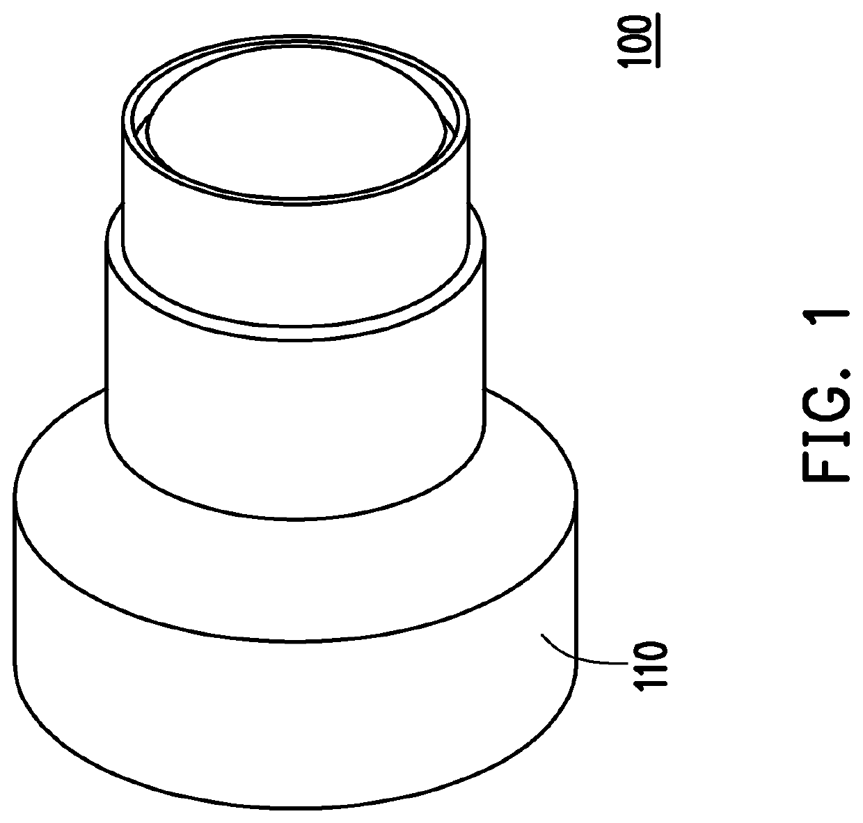
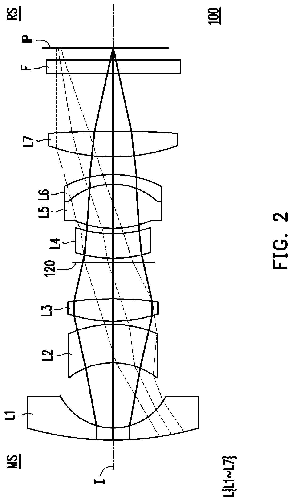
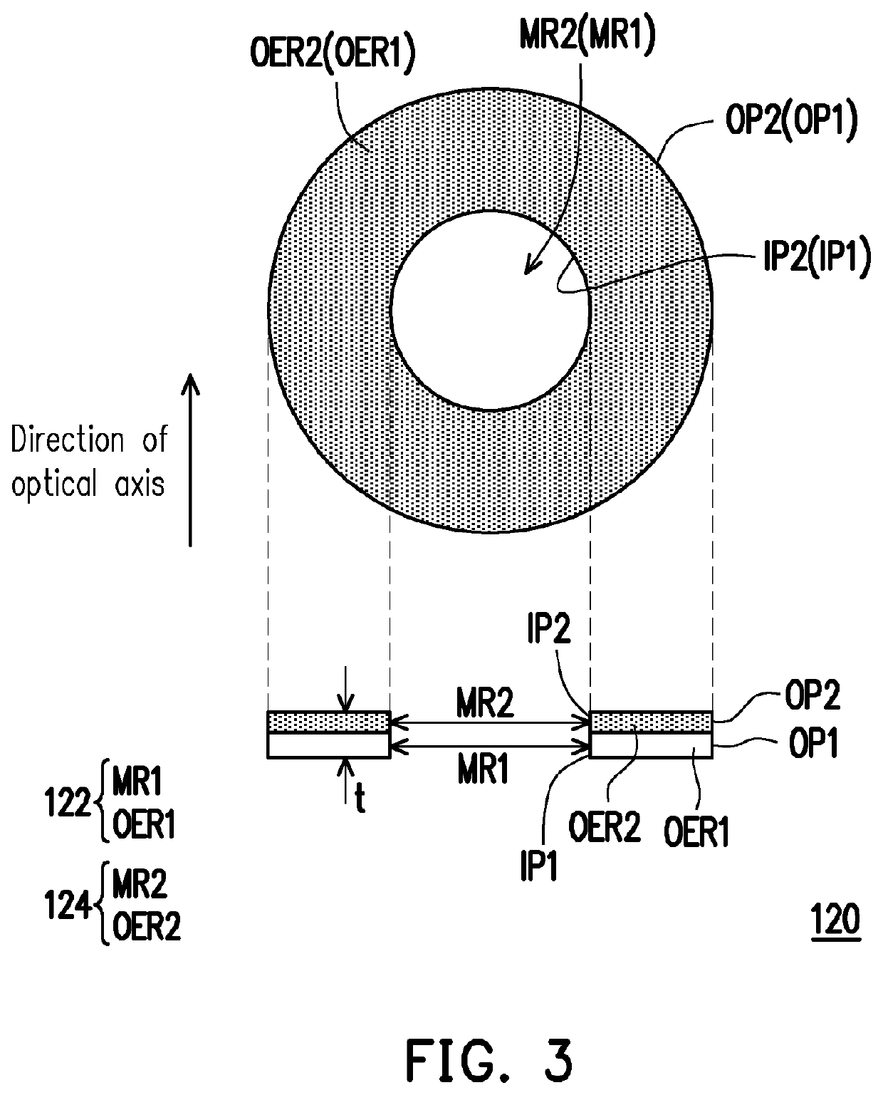
[0022]FIG. 1 is a schematic view of an appearance of an imaging lens according to one embodiment of the invention. FIG. 2 is an internal schematic view of the imaging lens of FIG. 1. FIG. 3 illustrates a top view and a cross-sectional view of an aperture in FIGS. 1 and 2. FIGS. 4A and 4B are equivalent optical schematic diagrams of the aperture in the imaging lens under viewing angles of image rays with different wavelength ranges, respectively. For conciseness, a barrel is omitted in FIG. 2, and each of FIG. 4A and FIG. 4B only illustrates an aperture and a barrel in the lens.

[0023]Referring to FIGS. 1 and 2, in the example, an imaging lens 100 has an optical axis I, which includes a barrel 110, lenses L1 to L7, and an aperture 120. The respective elements of the imaging lens 100 will be described in the following paragraphs, respectively.

[0024]In the example, the barrel 110 refers to an element for accommodating optical elements such as a lens piece (or a lens) and an aperture in ...


PUM


Abstract

An imaging lens including an aperture and a lens with refractive power arranged from a zoom-in side to a zoom-out side along an optical axis is provided. The aperture includes a substrate and a light-shielding layer. The substrate includes a first middle region and a first outer edge region surrounding the first middle region. The first outer edge region allows visible light and infrared light to substantially pass therethrough. The light-shielding layer includes a second middle region and a second outer edge region surrounding the second middle region. The second outer edge region allows infrared light to substantially pass therethrough and substantially shields visible light. A thickness of the aperture is between 0.01 mm and 0.3 mm along a direction of an optical axis. Furthermore, an imaging lens and a manufacturing method of a light-shielding element are also provided.

Description

CROSS-REFERENCE TO RELATED APPLICATION[0001]This application claims the priority benefit of Taiwan application serial no. 108132590, filed on Sep. 10, 2019. The entirety of the above-mentioned patent application is hereby incorporated by reference herein and made a part of this specification.BACKGROUND OF THE INVENTION1. Field of the Invention[0002]The invention generally relates to a lens and a manufacturing method of a light-shielding element, in particular, an imaging lens and a manufacturing method of a light-shielding element applied to the imaging lens.2. Description of Related Art[0003]In a common imaging lens, after an ambient ray enters the imaging lens, the ray passes through a lens group and an aperture in the imaging lens, and is finally transmitted to an image sensor for imaging. As the needs of users are diversified, variable apertures have been widely used in electronic products in order to achieve different photographing effects.[0004]In order to realize a variable a...

Claims


Application Information

Patent Timeline
Patent Type & Authority Patents(United States)
IPC IPC(8): G02B5/20G02B13/14G02B13/00
CPCG02B13/146G02B5/20G02B5/208G02B13/0015G02B5/005
Inventor LIN, MENG-WEILEE, CHEN-CHENG
Owner YOUNG OPTICS
Why Eureka
Try Eureka