Check patentability & draft patents in minutes with Patsnap Eureka AI!

Display device including a plurality of image adjustment circuits

a technology of image adjustment circuit and display device, which is applied in the direction of instruments, static indicating devices, etc., can solve the problem that the image adjustment process that has not normally been performed on the image data cannot be detected

Active Publication Date: 2022-07-12
TRIVALE TECH
View PDF22 Cites 0 Cited by
  • Summary
  • Abstract
  • Description
  • Claims
  • Application Information

AI Technical Summary

Benefits of technology

This approach allows the display device to accurately detect any deviations in the image adjustment process, preventing anomalies and ensuring the quality of the displayed image, particularly in safety-critical applications.

Problems solved by technology

Thus, whether the image adjustment process has normally been performed on the image data cannot be checked in the related configuration A. That is to say, the related configuration A has a problem in that an image adjustment process having not normally been performed on the image data cannot be detected.
On the other hand, when the image adjustment process is not normally performed by the first image adjustment element and / or the second image adjustment element, the first adjusted image data and the second adjusted image data do not match.

Method used


Image

  • Display device including a plurality of image adjustment circuits
  • Display device including a plurality of image adjustment circuits
  • Display device including a plurality of image adjustment circuits

Examples


embodiment 1

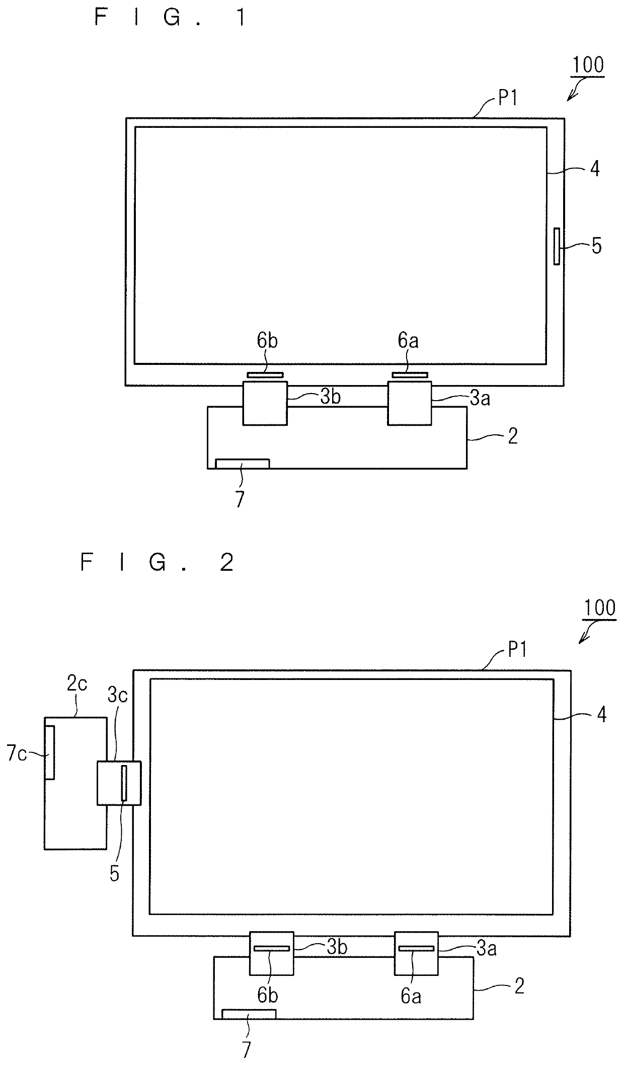
[0035]A display device relating to the present embodiment will be described below. FIG. 1 schematically illustrates a configuration of a display device 100 according to Embodiment 1. The display device 100 is, for example, a liquid crystal display. The display device 100 is not limited to the liquid crystal display. The display device 100 may, for example, be an organic electro-luminescence (EL) display.

[0036]Referring to FIG. 1, the display device 100 includes a display panel P1, a circuit board 2, and FPCs 3a and 3b. The FPCs are abbreviated names for flexible printed circuits. The display panel P1 is, for example, a liquid crystal panel. The FPCs 3a and 3b are arranged in parallel. The FPCs 3a and 3b connect the display panel P1 and the circuit board 2. The circuit board 2 and the FPCs 3a and 3b may be configured as a single FPC. In this configuration, the circuit board 2 is configured by a FPC.

[0037]The display panel P1 includes a pixel region 4, a gate driver IC 5, and source d...


PUM


Abstract

A display device performs a comparison process of comparing first adjusted image data and second adjusted image data. The first adjusted image data is adjusted image data obtained by a first image adjustment element performing an image adjustment process on image data to be processed. The second adjusted image data is adjusted image data obtained by a second image adjustment element performing the image adjustment process on the image data to be processed.

Description

BACKGROUND OF THE INVENTIONField of the Invention[0001]The present invention relates to a display device to adjust image data.Description of the Background Art[0002]A liquid crystal display typically includes a liquid crystal panel, a circuit board, and a flexible printed circuit (FPC). The FPC is a member to connect the liquid crystal panel and the circuit board.[0003]The liquid crystal panel includes a pixel region, a gate driver integrated circuit (IC), and a source driver IC (hereinafter, also referred to as an “S-IC”). The gate driver IC is disposed in a peripheral region of the pixel region along a vertical axis. The source driver IC is disposed in the peripheral region of the pixel region along a horizontal axis. The gate driver IC performs ON / OFF control of a thin film transistor (TFT) of a pixel.[0004]The circuit board includes a timing controller (hereinafter, also referred to as a “TCON”), ROM, an interface connector, a power supply circuit, and a tone reference voltage g...

Claims


Application Information

Patent Timeline
Patent Type & Authority Patents(United States)
IPC IPC(8): G09G3/34G09G3/36
CPCG09G3/3413G09G3/3648G09G2320/066G09G2320/0626G09G2320/0673G09G2330/021G09G3/2096G09G2320/0666G09G3/3607G09G2300/0447G09G2310/027
Inventor SAITO, YOSHIYANAKAMURA, AKINOBU
Owner TRIVALE TECH
Features
  • R&D
  • Intellectual Property
  • Life Sciences
  • Materials
  • Tech Scout
  • Unparalleled Data Quality
  • Higher Quality Content
  • 60% Fewer Hallucinations
Learn More