
Grow cabinet

a grow cabinet and grow chamber technology, applied in the field of grow cabinets, can solve the problems of inefficiency of conventional grow cabinets, inability to accurately control the temperature inside the grow chamber,

Active Publication Date: 2022-07-19
CRESCENT METAL PRODS
View PDF8 Cites 0 Cited by
  • Summary
  • Abstract
  • Description
  • Claims
  • Application Information

AI Technical Summary

Benefits of technology

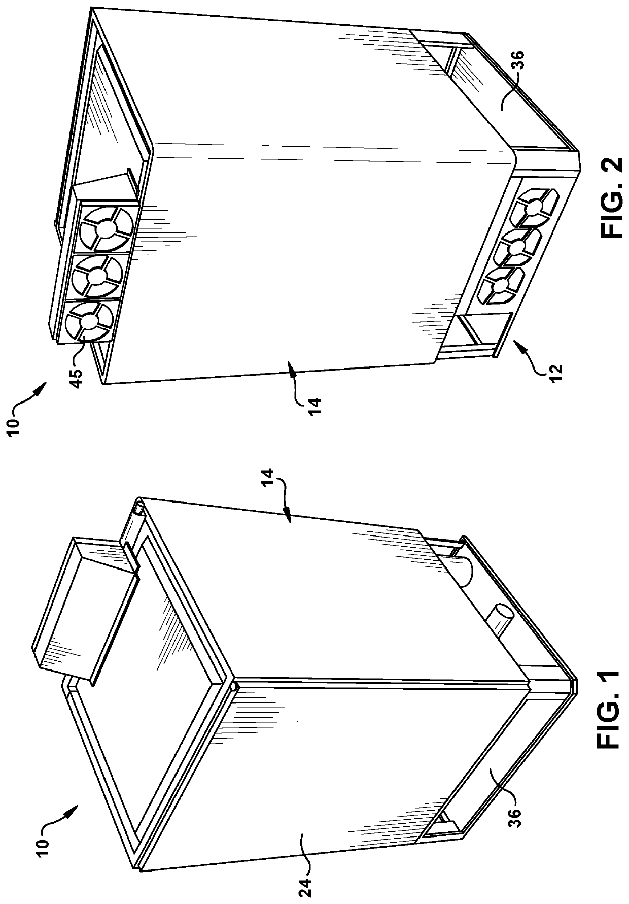
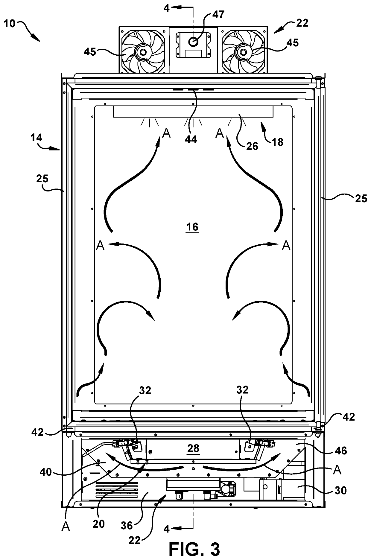
[0005]The present invention provides a temperature controlled cabinet, such as a grow cabinet, which provides accurate and precise temperature control of an internal chamber of the cabinet for maintaining items, such as plants, at a particular temperature.
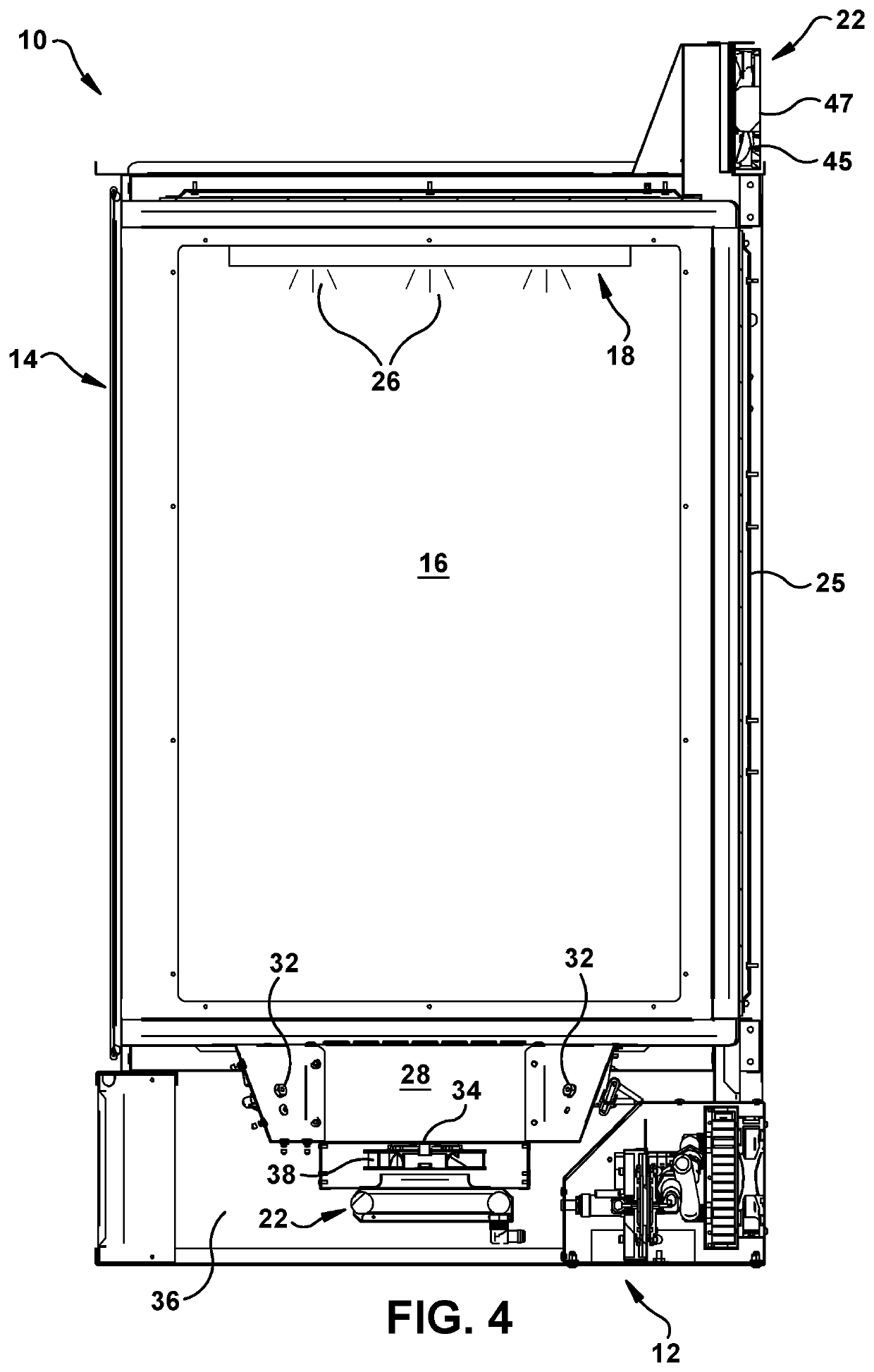
[0006]More particularly, the temperature controlled cabinet includes a thermoelectric temperature control system that enhances temperature accuracy and provides precise control of the temperature inside of the chamber, such as to facilitate growth of plants or the like inside of a grow chamber of the grow cabinet.
[0008]The work side of the thermoelectric heat exchanger assembly may be configured to maximize thermal transfer with an external environment on the ambient side, and may be configured to minimize thermal transfer with the external environment on the work side. Such a configuration minimizes thermal load on the work side during cooling of the grow chamber and maximizes thermal load on the ambient side during heating of the grow chamber to achieve a maximum differential in liquid temperatures on the opposite sides of the thermoelectric device. This enables the thermoelectric device to utilize its maximum potential in transferring heat between the respective liquid circuits, thereby enhancing accuracy in the temperature control.
[0009]More particularly, the thermoelectric heat exchanger assembly may be configured such that an overall thermal flux of the ambient side of the assembly is greater than an overall thermal flux of the work side of the assembly. For example, one or more parts of the thermoelectric heat exchanger assembly that form at least a portion of the ambient side may be made of high thermal conductivity material(s), while one or more parts of the assembly that form at least a portion of the work side may be made of low thermal conductivity material(s), thereby providing the difference in thermal conductivity and thermal transfer between the different sides of the assembly. Alternatively or additionally, the work side may include thermal insulation materials that further thermally insulate the work side relative to the ambient side to enhance efficiency.
[0010]According to another aspect of the invention, a temperature controlled cabinet such as a grow cabinet, includes: a housing; a chamber inside of the housing for containing items; and a thermoelectric temperature control system for controlling temperature inside the chamber, the thermoelectric temperature control system comprising: a work liquid circuit having a work heat exchanger in thermal communication with an environment inside of the chamber; an ambient liquid circuit having an ambient heat exchanger in thermal communication with an ambient environment outside of the chamber; and a thermoelectric heat exchanger assembly interposed between the work liquid circuit and the ambient liquid circuit, the thermoelectric heat exchanger assembly having: a work side having a work waterblock that at least partially forms a work liquid flow passage that is fluidly connected to the work liquid circuit; an ambient side having an ambient waterblock that at least partially forms an ambient liquid flow passage that is fluidly connected to the ambient liquid circuit; and a thermoelectric device interposed between the work liquid flow passage and the ambient liquid flow passage, the thermoelectric device having a first side in thermal communication with the work liquid flow passage, and having a second side that is in thermal communication with the ambient liquid flow passage for transferring heat between the ambient liquid circuit and the work liquid circuit; wherein the ambient waterblock is made of a first material, and the work waterblock is made of a second material, the first material of the ambient waterblock having a greater thermal conductivity than the second material of the work waterblock, such that thermal transfer with an external environment on the ambient side is maximized, and thermal transfer with the external environment on the work side is minimized.

Problems solved by technology

Typically grow cabinets are used when there is a lack of available outdoor space, or where the outdoor conditions are unsuitable for growing particular types of plants.
Conventional grow cabinets, however, are often inefficient and do not accurately control the temperature inside of the grow chamber.

Method used


Image

  • Grow cabinet
  • Grow cabinet
  • Grow cabinet

Examples


experiment 1

[0095]A solid aluminum heat sink cooled by an axial fan is connected to the hot side of the Peltier chip. A temperature of −12° F. is measured on the cold side of the Peltier chip, but unable to connect the chip to a working environment. The ambient environment temperature is 70-75° F.

experiment 2

[0096]Liquid is used on the hot side of the Peltier chip via a 3D-printed waterblock, aluminum heat spreader, centrifugal water pump, axial fan and a heat exchanger. A temperature of −14° F. is measured on the cold side, but unable to connect the chip to a working environment. The ambient environment temperature is 70-75° F.

experiment 3

[0097]Liquid is used on both sides of the chip using two plastic 3D-printed waterblocks, centrifugal pumps, and aluminum heat spreaders on the opposing sides of the Peltier chip. The hot side of the Peltier chip also includes a heat exchanger and an axial fan. The liquid on the cold side is measured to be −15° F. with no load (not connected to working environment). The ambient environment temperature is 70-75° F.


PUM


Abstract

A thermally controlled cabinet such as a grow cabinet having an internal chamber for containing objects such as plants, with a temperature control system that accurately and precisely maintains the temperature inside of the chamber.

Description

RELATED APPLICATIONS[0001]This application claims the benefit of U.S. Provisional Application No. 62 / 867,559 filed Jun. 27, 2019, which is hereby incorporated herein by reference in its entirety.FIELD OF INVENTION[0002]The present invention relates to a grow cabinet having a grow chamber with lighting and temperature control for facilitating the growth of plants or the like in the grow chamber, and more generally to a cabinet having a chamber for containing items, with the provision of precise temperature control of the chamber.BACKGROUND[0003]Grow cabinets, sometimes referred to as grow boxes or cultivation cabinets, are used to recreate and control an environment for growing plants indoors or in small areas. Typically grow cabinets are used when there is a lack of available outdoor space, or where the outdoor conditions are unsuitable for growing particular types of plants. Grow cabinets also can help to protect plants against disease or pests.[0004]Typically a grow cabinet will i...

Claims


Application Information

Patent Timeline
Patent Type & Authority Patents(United States)
IPC IPC(8): A01G9/24F25B21/04
CPCA01G9/246A01G9/247A01G9/249F25B21/04A01G2009/248F25B2321/021F25B2321/023A01G31/02F25B2321/0252F25B2321/0212
Inventor BOWLES, JOHN L.
Owner CRESCENT METAL PRODS
Learn More