Vehicle wheel
a technology for vehicles and wheels, applied in the field of vehicles, can solve problems such as insufficient reduction of noise caused, and achieve the effect of sufficiently reducing the noise caused by pipe resonan
- Summary
- Abstract
- Description
- Claims
- Application Information
AI Technical Summary
Benefits of technology
Problems solved by technology
Method used
Image
Examples
second embodiment
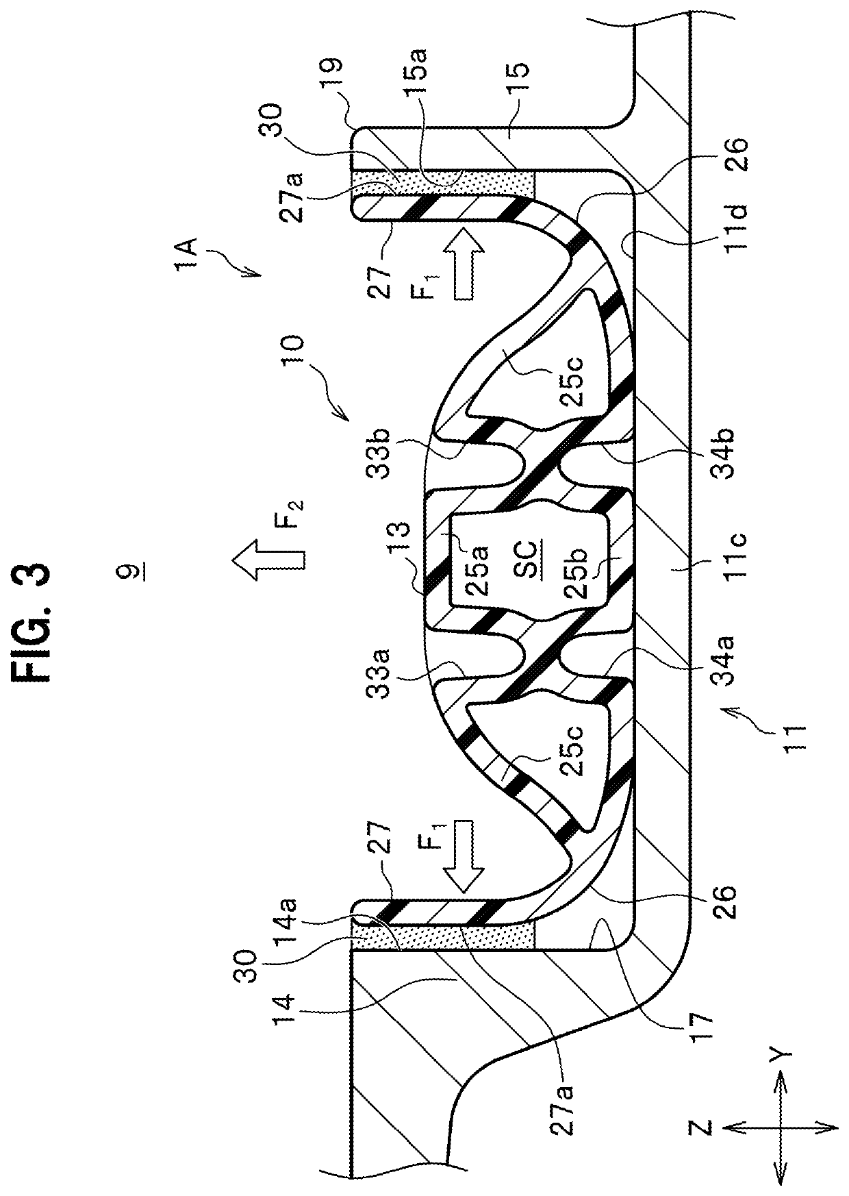
[0058]Next, the vehicle wheel of a second embodiment of the present invention is described with focusing on difference from the vehicle wheel 1A according to the first embodiment. As illustrated in FIG. 5, according to a vehicle wheel 1B of a second embodiment of the present invention, the surface roughness of the side surface 14a of the vertical wall 14 is determined given that it is possible to more preferably prevent detachment of the Helmholtz resonator 10 which is to be caused by centrifugal force, through increasing an adhesion area of the side surface 14a fixed to the adhesive layer 30 (the same applies to the side surface 15a of the vertical wall 15). This surface roughness is increased by surface processing.
[0059]
[0060]Next, the operational advantage provided by the vehicle wheel 1B of this embodiment is described.
[0061]The vehicle wheel 1B of this embodiment has a feature that surface processing is performed and the surface roughnessess of the side surfaces 14a, 15a of the...
third embodiment
[0063]Next, the vehicle wheel of a third embodiment of the present invention is described with focusing on difference from the vehicle wheel 1A according to the first embodiment. Although there is no particular illustration, according to a vehicle wheel of the third embodiment of the present invention, the surface roughness of the outward surface 27a (see FIG. 3) of each of the opposite wall portions 27, 27 is determined, given that it is possible to more preferably prevent detachment of the Helmholtz resonator 10 which is to be caused by centrifugal force, through increasing adhesion areas of the outward surfaces 27a, 27a fixed to the adhesive layers 30, 30. The surface roughnessess are increased by surface processing.
[0064]
[0065]Next, the operational advantage provided by the vehicle wheel of this embodiment is described.
[0066]According to this vehicle wheel, the adhesion areas of the pair of opposite wall portions 27, 27 fixed to the adhesive layers 30, 30 are increased, and thus...
fourth embodiment
[0067]Next, the vehicle wheel of a fourth embodiment of the present invention is described with focusing on difference from the vehicle wheel 1A according to the first embodiment. As illustrated in FIG. 6, according to a vehicle wheel 1C of the fourth embodiment of the present invention, a thread portion 14b is formed at the side surface 14a of the vertical wall 14 (the same applies to the vertical wall 15). Thread grooves of the thread portion 14b extend in the wheel circumferential direction. That is, at the side surface 14a, protrusion portions and recess portions of the thread portion 14b are alternately formed in the wheel radial direction. The thread portion 14b is shallower than a conventional circumferential groove formed by a conventional art and is formed by surface processing of the side surface 14a.
[0068]
[0069]Next, the operational advantage provided by the vehicle wheel 1C of this embodiment is described.
[0070]The vehicle wheel 1C of this embodiment has a feature that ...
PUM
 Abstract
Description
Claims
Application Information
 - R&D
- Intellectual Property
- Life Sciences
- Materials
- Tech Scout
- Unparalleled Data Quality
- Higher Quality Content
- 60% Fewer Hallucinations
Browse by: Latest US Patents, China's latest patents, Technical Efficacy Thesaurus, Application Domain, Technology Topic, Popular Technical Reports.
© 2025 PatSnap. All rights reserved.Legal|Privacy policy|Modern Slavery Act Transparency Statement|Sitemap|About US| Contact US: help@patsnap.com


