
Valve device and steam turbine

a valve device and steam turbine technology, applied in valve details, valve arrangements, thin material handling, etc., can solve the problems of affecting the movement of the rod, deteriorating the assembly property, and scaling to the rod

Active Publication Date: 2022-08-16
MITSUBISHI HEAVY INDUSTIES COMPRESSOR CORP
View PDF23 Cites 2 Cited by
  • Summary
  • Abstract
  • Description
  • Claims
  • Application Information

AI Technical Summary

Benefits of technology

The configuration enhances the stability and accuracy of rod movement, reduces the overall size of the valve device, and improves assembling properties by simplifying the internal structure and preventing scale-induced clogs, thereby improving the efficiency and reliability of the steam turbine.

Problems solved by technology

On the contrary, for example, in the case where a structure in which the rod of the main steam stop valve is movable in the vertical direction while being parallel to the rod of the steam-regulating valve is adopted, the shapes of a flow path of the main steam stop valve and a flow path of the steam-regulating valve, which are formed in a valve casing, become complicated by being curved a plurality of times. As a result, there is a deterioration in assembling property at the time of incorporation of a valve seat, a valve body, or the like to be disposed in the valve casing.
However, there is a possibility that scale adheres to the rod due to the influence of steam flowing in the valve device.
Therefore, there is a possibility that a region around the rod with a narrow clearance is clogged with the scale and the movement of the rod is impeded.

Method used


Image

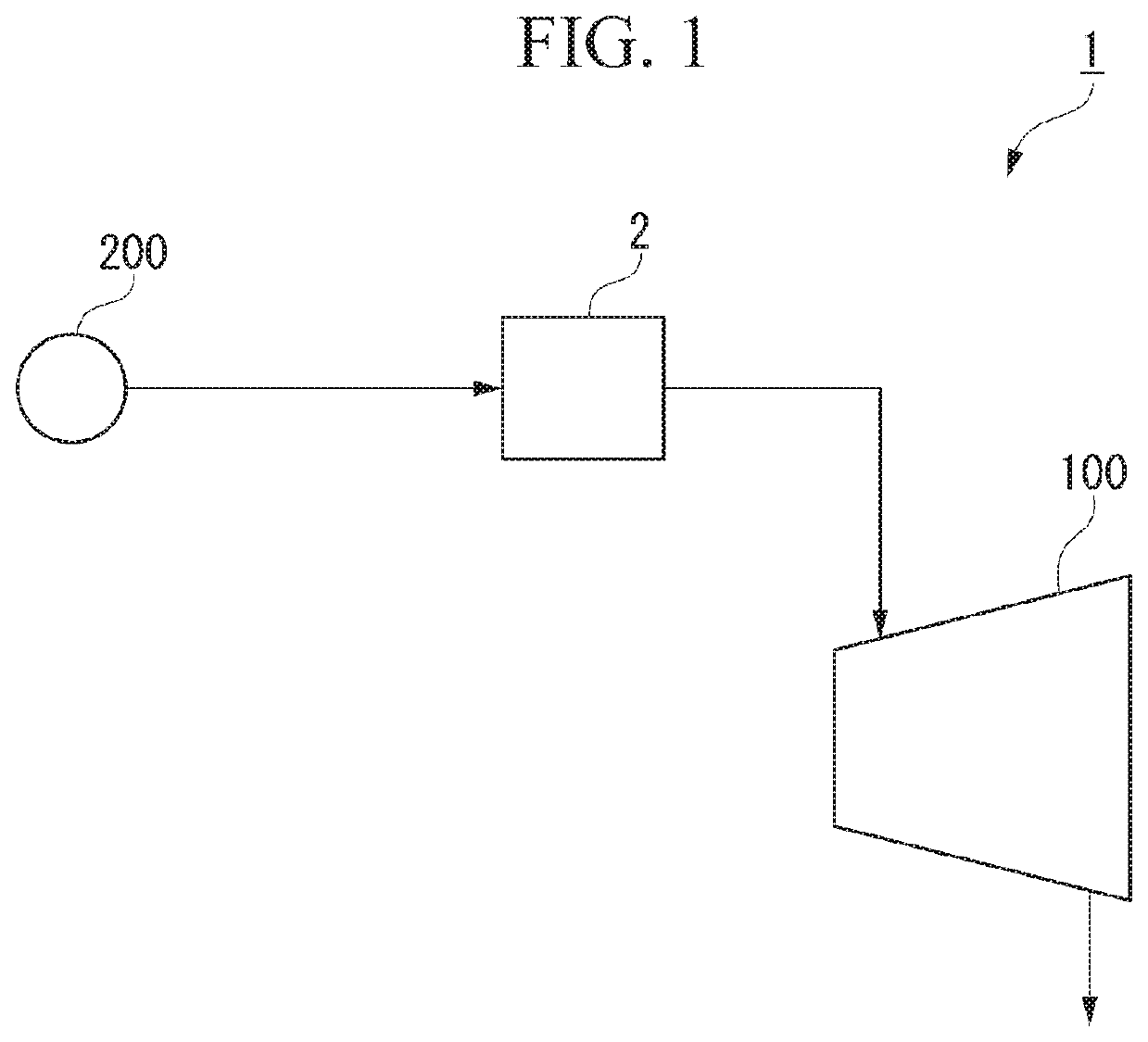
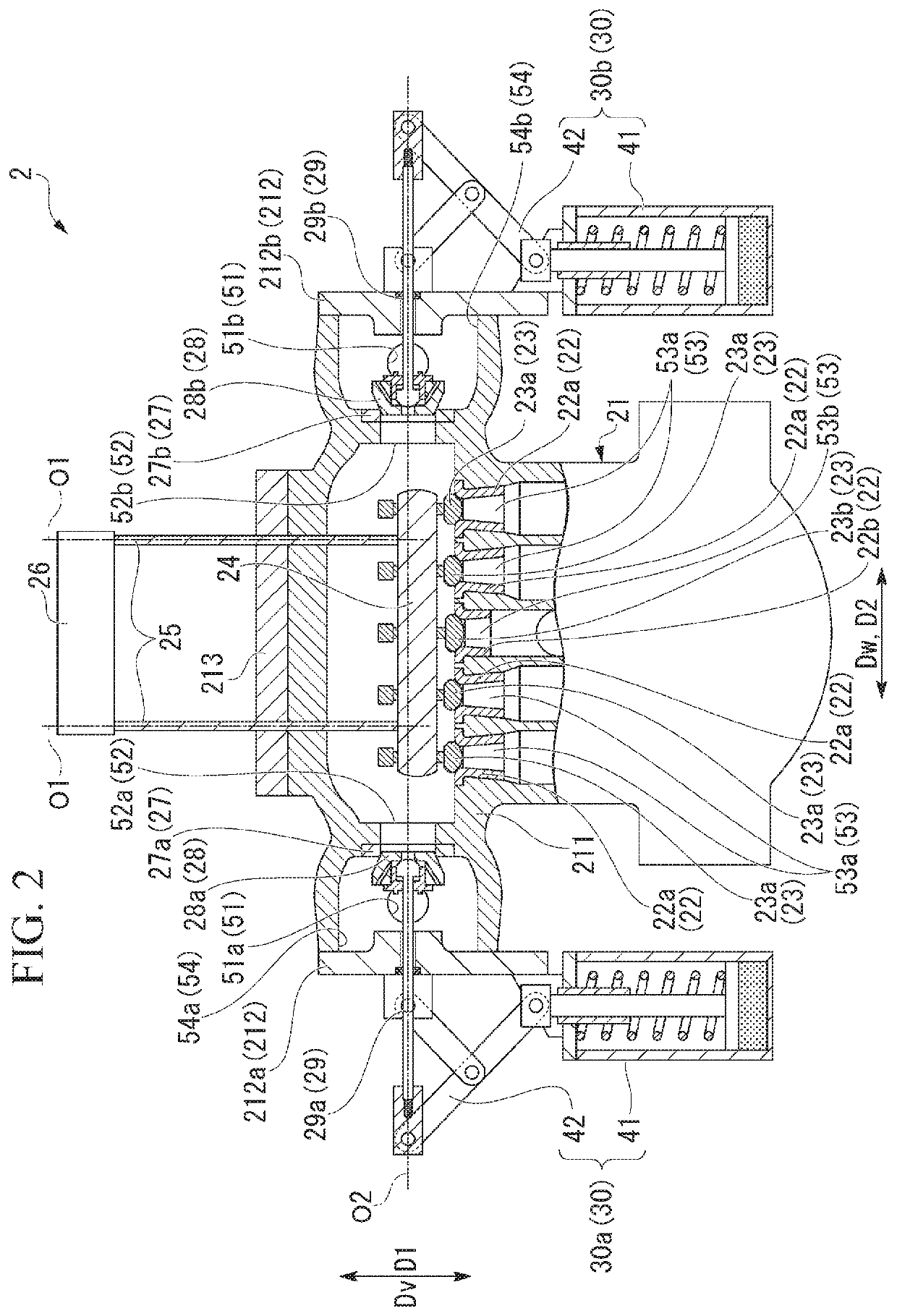
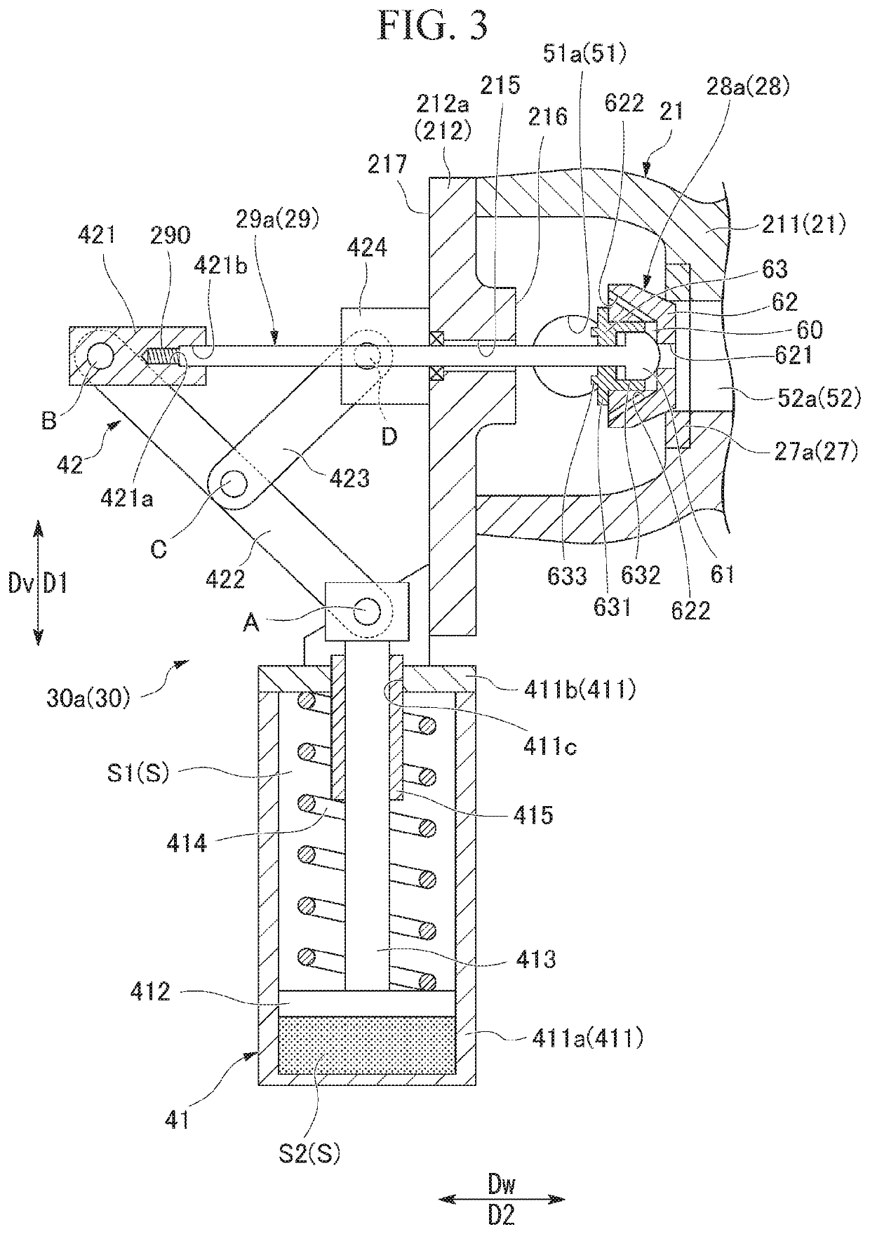
  • Valve device and steam turbine
  • Valve device and steam turbine
  • Valve device and steam turbine

Examples


modification examples of embodiment

Other Modification Examples of Embodiment

[0088]While preferred embodiments of the invention have been described and illustrated above, it should be understood that these are exemplary of the invention and are not to be considered as limiting. Additions, omissions, substitutions, and other modifications can be made without departing from the spirit or scope of the present invention. Accordingly, the invention is not to be considered as being limited by the foregoing description, and is only limited by the scope of the appended claims.

[0089]Note that, one valve casing main body 211 may not be provided with the plurality of inlet flow paths 51, the plurality of intermediate flow paths 52, the plurality of outlet flow paths 53, and the plurality of external opening portions 54 as in the present embodiment. For example, one valve casing main body 211 may be provided with one inlet flow path 51, one intermediate flow path 52, one outlet flow path 53, and one external opening portion 54 an...


PUM


Abstract

A valve device includes a valve casing 21, an intermediate rod portion 29, and an intermediate actuator unit 30. In the valve casing 21, a rod insertion hole into which the intermediate rod portion 29 can be inserted is formed. The intermediate actuator unit 30 includes a hydraulic cylinder that causes a piston rod portion to advance and retreat in a direction orthogonal to a second center axis direction D2. The hydraulic cylinder includes a rod guide portion that guides movement of the piston rod portion. A gap between an inner circumferential surface of the rod insertion hole and an outer circumferential surface of the intermediate rod portion 29 is formed to be wider than a gap between an inner circumferential surface of the rod guide portion and an outer circumferential surface of the piston rod portion.

Description

BACKGROUND OF THE INVENTIONField of the Invention[0001]The present invention relates to a valve device and a steam turbine.[0002]Priority is claimed on Japanese Patent Application No. 2019-031740, filed on Feb. 25, 2019, the content of which is incorporated herein by reference.Description of Related Art[0003]A steam turbine rotates and drives a rotor by means of steam supplied from a boiler. The steam turbine transmits the rotation of the rotor to operate a compressor or a generator.[0004]In the steam turbine, an adjusting valve or a stop valve is provided to supply steam from the boiler to a turbine main body. The flow rate of steam supplied to the turbine main body can be adjusted by adjusting the opening degree of the adjusting valve. In addition, at the time of a normal operation of the steam turbine, the stop valve is in an opened state. Accordingly, steam is supplied to the turbine main body from the boiler through a steam supply pipe. In addition, in the case where an abnorma...

Claims


Application Information

Patent Timeline
Patent Type & Authority Patents(United States)
IPC IPC(8): F01D17/14F16K31/44F01D17/10F01D17/18F01D25/24
CPCF01D17/145F16K31/44F01D17/10F01D17/18F01D25/24F05D2220/31F05D2220/72Y10T137/87917
Inventor NISHIYAMA, KENICHI
Owner MITSUBISHI HEAVY INDUSTIES COMPRESSOR CORP
Learn More