Operational constraints for operational functions of field devices

Active Publication Date: 2022-08-16
SIEMENS AG
View PDF7 Cites 0 Cited by
  • Summary
  • Abstract
  • Description
  • Claims
  • Application Information

AI Technical Summary

Benefits of technology

[0016]By writing the operational state referenced to the operational function to the dDB, it is possible to facilitate a later check for the fulfilment of the operational constraint based on a comparison between the operational state and the operational constraint. For example, it can be checked—based on the information available in the dDB—whether the operational state was within certain boundaries imposed by the operational constraint. This is achieved in a tamper-proof manner, because the dDB typically offers a high level of security.
[0019]By using a sensor remote of the field device, security against corruption of the state signal can be increased.
[0021]This can simplify the architecture; for example, a third-party sensor may not be required.
[0027]Such techniques described in connection with the further state signal facilitate tracking whether the operational constraint is appropriately fulfilled in view of one or more trigger criteria for conditionally activating / deactivating the operational constraint.
[0039]Thereby, it becomes possible to securely log activation / deactivation or (re-)configuration of the operational constraint.

Problems solved by technology

Currently, a transparent view on VNF configurations is not given by systems which always is a problem as soon as more stakeholders are involved—that is typically the case in existing and future scenarios with many field devices being connected while delivering data, as well as communication services.

Method used


Image

  • Operational constraints for operational functions of field devices
  • Operational constraints for operational functions of field devices
  • Operational constraints for operational functions of field devices

Examples


Embodiment Construction

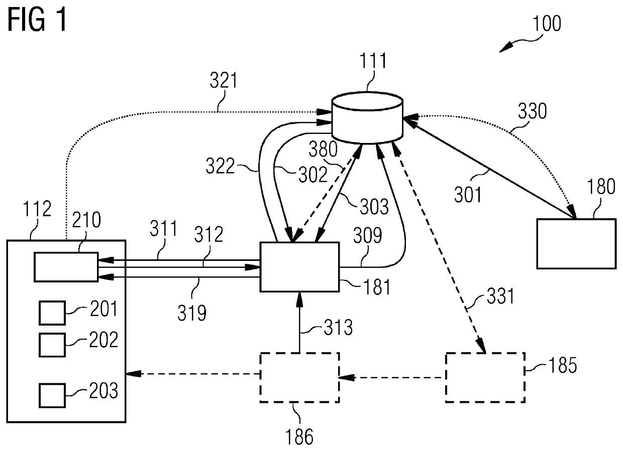
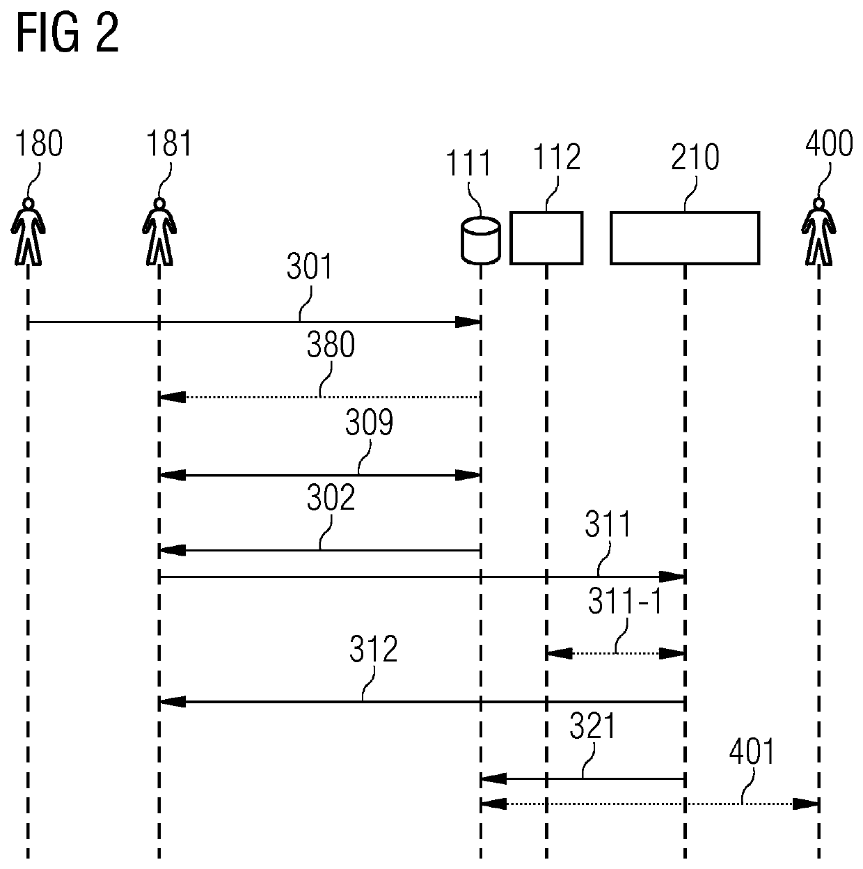
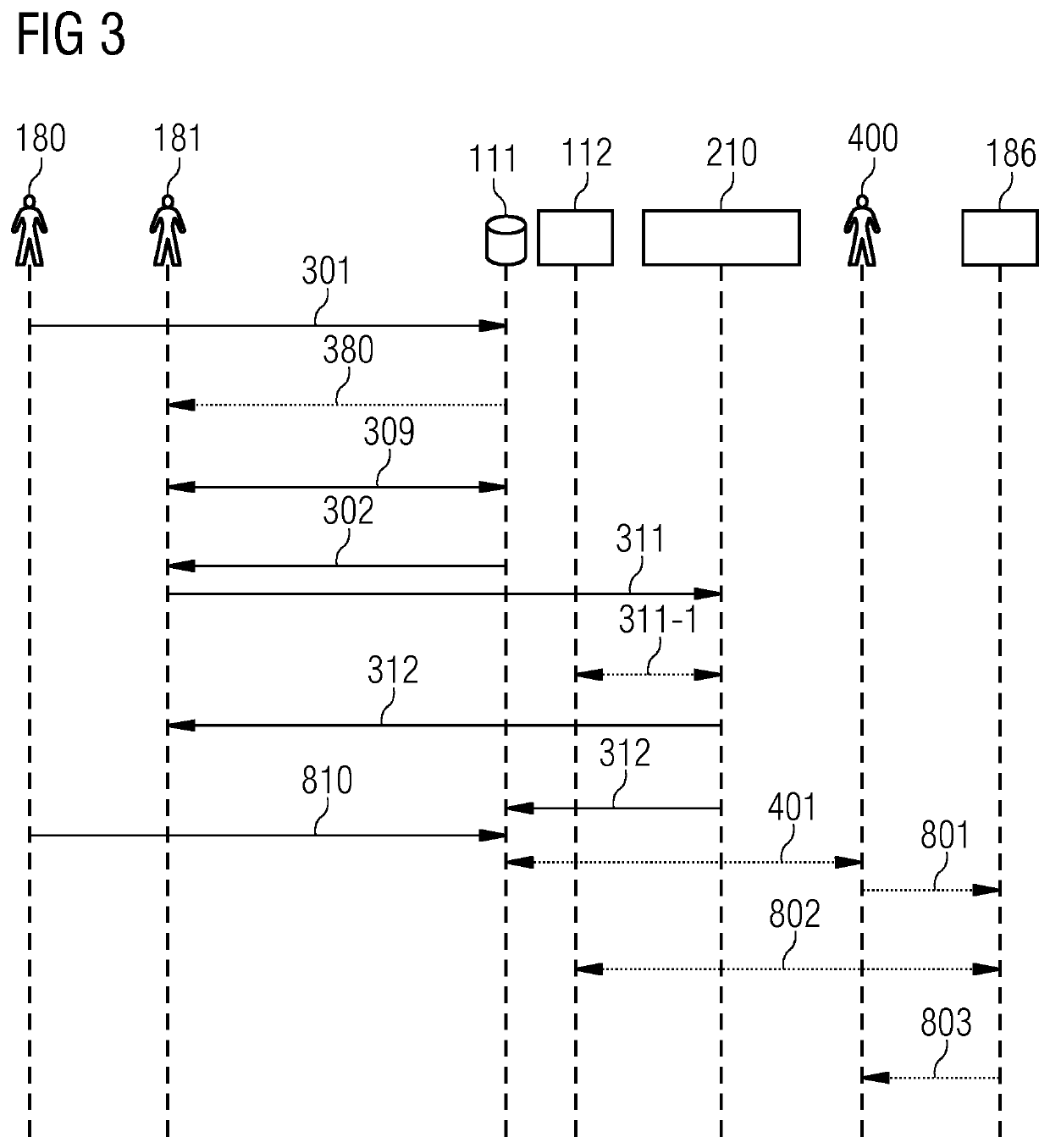
[0051]In the following, various embodiments of the invention will be described in detail with reference to the appended figures it is to be understood that the following description of embodiments is not to be taken in a limiting sense. The scope of embodiments of the invention is not intended to be limited by the embodiments described hereinafter or by the figures, which are taken to be illustrative only.

[0052]The figures are to be regarded as being schematic representations and elements illustrated in the figures, which are not necessary the scope shown to scale. Rather, the various elements are represented such that their function and debt general purpose become apparent to a person skilled in the art. Any connection or coupling between functional blocks, devices, components or other physical or functional units shown in the figures or described herein may also be implemented by an indirect connection or coupling. A coupling between components may be established over a wireless c...


PUM


Abstract

According to various examples, an operational constraint associated with an operational function—e.g., a virtual network function—implemented on a field device can be configured. According to further examples, the fulfillment of the operational constraint can be tracked. For these purposes, a distributed database is used, e.g., a blockchain.

Description

CROSS-REFERENCE TO RELATED APPLICATIONS[0001]This application claims priority to PCT Application No. PCT / EP2019 / 071117, having a filing date of Aug. 6, 2019, which is based on EP Application No. 18187781.2, having a filing date of Aug. 7, 2018, the entire contents both of which are hereby incorporated by reference.FIELD OF TECHNOLOGY[0002]Various examples of embodiments of the invention generally relate to operational constraints for operational functions implemented on field devices. Various examples specifically relate to configuring the operational constraints and tracking fulfillment of the operational constraints.BACKGROUND[0003]Field devices with communication capabilities sometimes implement features through virtual network functions. Virtual network functions (VNF) offer a lot more flexibility if compared to traditional approaches, but also require close monitoring and tracking of configurations in order to avoid undesired or even malicious configurations that endanger integ...

Claims


Application Information

Patent Timeline
Patent Type & Authority Patents(United States)
IPC IPC(8): G06F16/182H04L41/5009H04L9/06H04L67/101H04L67/1023
CPCH04L41/5009G06F16/182H04L9/0643H04L67/101H04L67/1023H04L2209/38H04L41/069H04L41/0816H04L41/5054H04L43/08H04L43/0817H04L63/123H04L41/0895H04L41/40H04L43/20H04L9/50
Inventor SAUER, MARKUSZEIGER, FLORIAN
Owner SIEMENS AG
Why Eureka
Try Eureka