Unlock instant, AI-driven research and patent intelligence for your innovation.

Method and device for fitting an angular contact roller bearing

a technology of angular contact and roller bearing, which is applied in the direction of rolling contact bearings, shafts and bearings, rotary bearings, etc., can solve the problems of overdimensioning in terms of load capacity, high production cost of cylindrical roller bearings of this kind, and always subject to certain limits of deep groove ball bearings

Active Publication Date: 2022-10-04
SCHAEFFLER TECH AG & CO KG
View PDF38 Cites 0 Cited by
  • Summary
  • Abstract
  • Description
  • Claims
  • Application Information

AI Technical Summary

Benefits of technology

The invention aims to provide a simple and cost-effective assembly method for a single-row angular contact roller bearing with rims that delimit the race on one side in each case. The design of the rims ensures that high axial forces during operation can be absorbed in one direction with a minimum friction while lower axial forces can be absorbed in the other direction via the oblique races. The ramp part has a sloping flat slideway which allows for accurate assembly of the inner bearing ring into the outer bearing ring. The load capacity of the bearing is higher than a single-row deep groove ball bearing and higher than a single-row cylindrical roller bearing of similar size. The design eliminates the need for separate rim disks and reduces assembly effort, resulting in lower overall costs for bearing manufacture.

Problems solved by technology

In practice, however, it has been found that deep groove ball bearings of this kind are always subject to certain limits, especially in respect of the radial load capacity of the bearing, due to the low maximum number of bearing balls that can be installed, this being dependent on the dimensions of the inner and the outer bearing ring and on the diameter of the bearing balls.
In the past, therefore, a large number of solutions, e.g. an unclosed feed opening arranged in the opposite rims of the races of the outer and the inner bearing ring in accordance with DE 151 483 A1 or a closable feed opening of similar design in accordance with DE 24 07 477 A1, have been proposed, the intention being, by these openings, to achieve an increase in the radial load capacity of deep groove ball bearings by increasing the number of bearing balls, although they have not found acceptance in practice owing to the disadvantages resulting from such feed openings.
However, due to the high proportion of machining involved, especially in the production of the races and the machining of the rims, cylindrical roller bearings of this kind have very high production costs and would, in turn, furthermore be overdimensioned in terms of their load capacity, making them ultimately unsuitable for use as fixed bearings in manual transmissions of motor vehicles.
Although, in the case of angular contact roller bearings of this kind, the fact that only one of the bearing rings is formed integrally with just one lateral rim means that the proportion of machining in the production of the races and the machining of the rims and hence also the overall costs for bearing manufacture are significantly lower than in the case of the cylindrical roller bearing described above, the formation of the rim on the other bearing ring as a separate rim disk, the additional installation thereof on this bearing ring and the required precision manufacture of the contact surfaces on these and on the associated bearing ring in the case of these angular contact roller bearings have an unfavorable effect on the production costs thereof.
Moreover, there is the risk in the case of these angular contact roller bearings that the separate rim disk will not be sufficiently well secured to withstand high radial or axial load spikes, with the result that the rim disk may become detached during the operation of the bearing and ultimately the bearing may fail.

Method used


Image

  • Method and device for fitting an angular contact roller bearing
  • Method and device for fitting an angular contact roller bearing
  • Method and device for fitting an angular contact roller bearing

Examples


Embodiment Construction

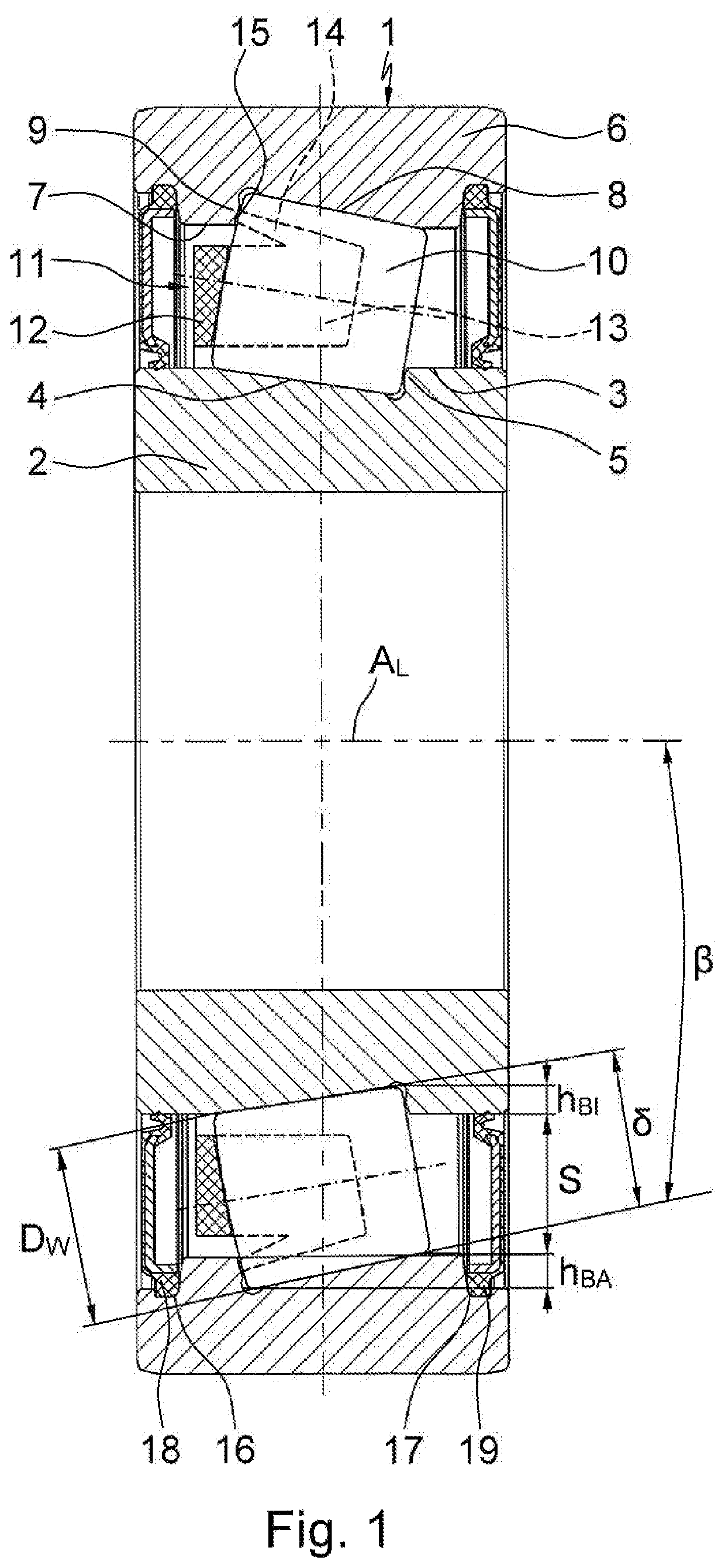
[0040]FIG. 1 illustrates a cross section of a single-row angular contact roller bearing 1, which is suitable, for example, as a replacement for the hitherto used deep groove ball bearing for supporting the crankshaft in motor-vehicle internal combustion engines. As is clearly apparent, this angular contact roller bearing 1 comprises an inner bearing ring 2 having an inner race 4 arranged on the outer peripheral surface 3 thereof and inclined with respect to the bearing rotation axis AL, which is delimited at its smallest diameter by a rim 5, and an outer bearing ring 6 having an outer race 8 arranged on the inner peripheral surface 7 thereof and likewise inclined with respect to the bearing rotation axis AL, which is delimited at its largest diameter by a rim 9. A multiplicity of roller bearing elements 10, which roll on the races 4, 8 thereof and are held at uniform distances from one another in the circumferential direction by a bearing cage 11, are furthermore arranged between th...


PUM


Abstract

A method and device for fitting an angular contact roller bearing, including an inner bearing ring having an inner race arranged on the outer peripheral surface of the inner bearing ring and inclined with respect to the axis of rotation of the bearing, and a rim delimiting said race at the smallest diameter thereof, an outer bearing ring having an outer race arranged on the inner peripheral surface of the outer bearing ring and inclined with respect to the axis of rotation of the bearing, and a rim delimiting said race at the greatest diameter thereof, and also including a plurality of roller bearing elements arranged between the bearing rings and roll on the races and are held at uniform distances from one another in the circumferential direction by a bearing cage. The outer peripheral surface of the inner bearing ring and the inner peripheral surface of the outer bearing ring are in each case cylindrical and extend outside the races at least in some sections coaxially with respect to the axis of rotation of the bearing, and the races of both bearing rings are in each case integrated conically into the cylindrical peripheral surfaces, such that the rims which are produced and in each case delimit the races on one side are in each case formed in one piece with the bearing rings. The fitting of the angular contact roller bearing takes place according to an eccentric pivot fitting method the deep groove ball bearing eccentric fitting method.

Description

[0001]The invention relates to a method for assembling an angular contact roller bearing, in particular a single-row angular contact roller bearing, which can be used to particular advantage to support the crankshaft in a motor-vehicle internal combustion engine. The invention furthermore relates to a device for assembling the angular contact roller bearing.BACKGROUND[0002]The type of bearing most often used to support the crankshaft in motor-vehicle internal combustion engines is the single-row deep groove ball bearing since this bearing is distinguished by an equally high radial and axial load capacity and has the highest rotational speed limits of all types of bearing because of its low friction. As is known, this deep groove ball bearing comprises an outer bearing ring, an inner bearing ring and a multiplicity of bearing balls, which are arranged between the bearing rings, roll in races in the form of grooves machined into the inside of the outer bearing ring and the outside of ...

Claims


Application Information

Patent Timeline
Patent Type & Authority Patents(United States)
IPC IPC(8): F16C19/36F16C43/08F16C33/46F16C33/49
CPCF16C43/08F16C19/36F16C33/4605F16C33/495F16C43/06F16C19/364F16C33/585
Inventor EIDLOTH, RAINERRUMPEL, REINHARDGEIGER, ERNSTHOFMANN, HEINRICH
Owner SCHAEFFLER TECH AG & CO KG