Microfluidic dispenser device for delivering inhalable substances

a dispenser device and microfluidic technology, applied in the direction of inhalators, other medical devices, tobacco, etc., can solve the problems of inhalation of inhalable substances, inability to deliver inhalable substances, and release of undesirable and potentially harmful substances,

Active Publication Date: 2022-11-01
STMICROELECTRONICS SRL
View PDF17 Cites 1 Cited by
  • Summary
  • Abstract
  • Description
  • Claims
  • Application Information

AI Technical Summary

Benefits of technology

[0007]At least one embodiment of the present disclosure is a microfluidic dispenser device for delivering inhalable substances that will enable at least some of the limitations described above to be overcome or at least mitigated.

Problems solved by technology

Delivery devices of this sort suffer from certain limitations.
In the first place, the electrode is directly in contact with the fluid to be delivered, and this may lead to release of undesirable and potentially harmful substances.
Such a condition may trigger reactions in the fluid that alter the substances to be delivered.
If the substances to be delivered are drugs, the reactions may render the active principles inefficacious.
If, instead, the device delivers surrogates of smoke, the organoleptic characteristics may be degraded.
In the worst scenarios, the reactions due to the high temperature may produce harmful substances that are inhaled to the detriment of the user.
A further limit of known devices is the low precision in controlling the doses of inhalable substances delivered.
Actuators of this type do not present problems linked to the release of substances from the coil (which is not in contact with the liquid) and to the excessive heating, but are costly and not suited to being integrated in disposable cartridges, as would be preferable.

Method used


Image

  • Microfluidic dispenser device for delivering inhalable substances
  • Microfluidic dispenser device for delivering inhalable substances
  • Microfluidic dispenser device for delivering inhalable substances

Examples


Embodiment Construction

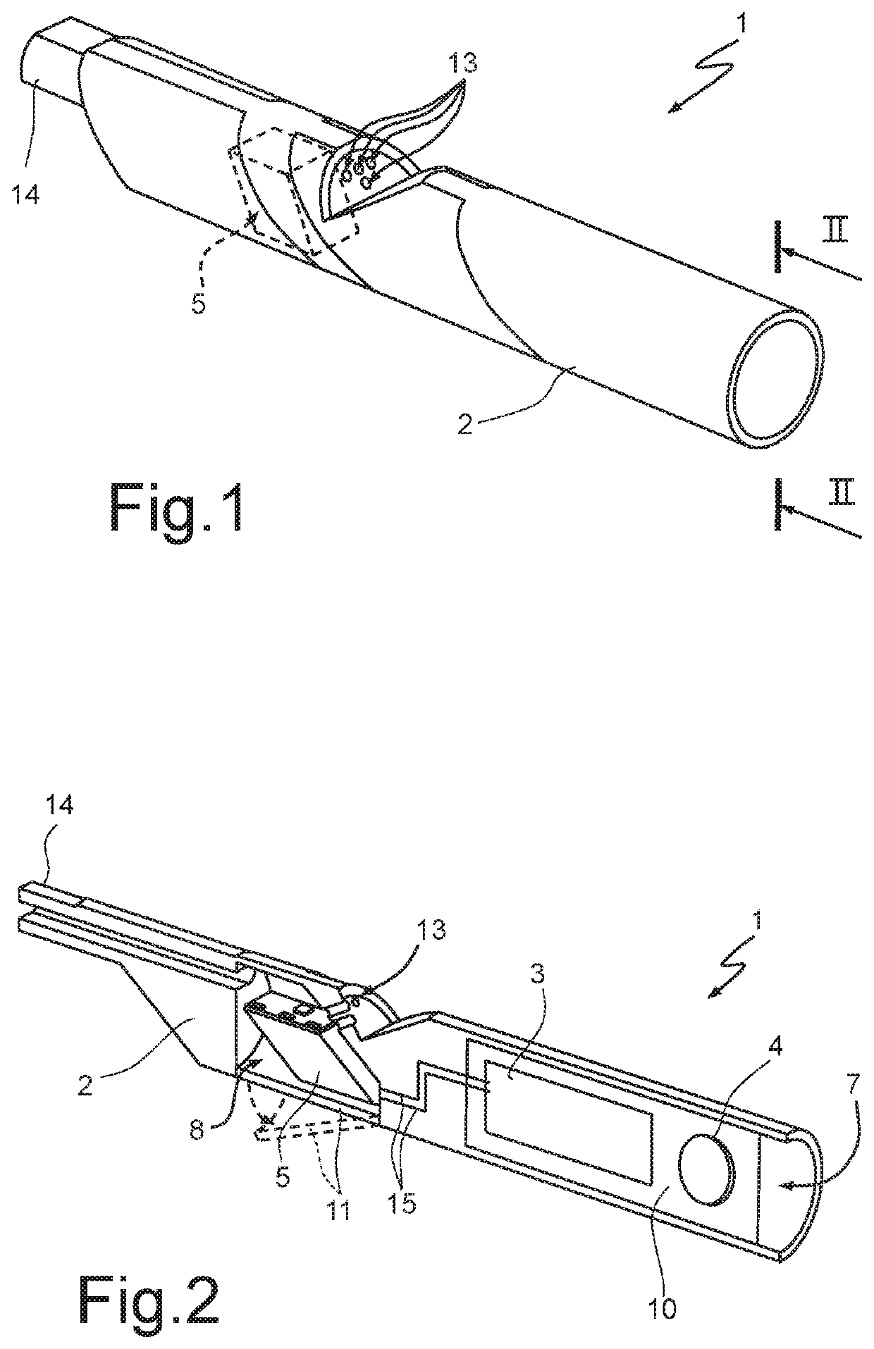
[0027]With reference to FIGS. 1 and 2, number 1 designates as a whole a microfluidic dispenser device for delivering inhalable substances, which in the embodiment illustrated is an electronic cigarette. The microfluidic delivery device 1 comprises a casing 2, housed within which are a driving device 3, a battery 4, and a disposable microfluidic cartridge 5.

[0028]In greater detail, the casing 2 comprises an elongated tubular body 6 made of polymeric and / or metal material, and includes a control housing 7 and a cartridge housing 8. In one embodiment, the control housing 7 defines a substantially axial blind cavity 7A, which is open at a first end 2a of the casing 2 and may be closed, for example, with an appropriately designed lid (not illustrated). The driving device 3 may be welded on a support 10, for example a PCB (printed circuit board) that may be inserted in the cavity 7A in the control housing 7 together with the battery 4.

[0029]The cartridge housing 8 encloses a chamber 8A se...


PUM

PropertyMeasurementUnit
diameteraaaaaaaaaa
temperatureaaaaaaaaaa
areaaaaaaaaaaa

Abstract

A microfluidic dispenser device of inhalable substances includes a casing, housed in which are a driving circuit and a microfluidic cartridge having a tank that contains a liquid to be delivered. The microfluidic cartridge is provided with at least one nebulizer controlled by the driving device. The nebulizer includes: a substrate; a plurality of chambers formed on the substrate and fluidically coupled to the tank for receiving the liquid to be delivered; and a plurality of heaters, which are formed on the substrate in positions corresponding to respective chambers, are thermally coupled to the respective chambers and are separated from the respective chambers by an insulating layer, and are controlled by the driving device. Each chamber is fluidically connected with the outside by at least one respective nozzle.

Description

BACKGROUNDTechnical Field[0001]The present disclosure relates to a microfluidic dispenser device for delivering inhalable substances.Description of the Related Art[0002]As is known, the need to control precisely delivery of inhalable substances, both for therapeutic purposes and for the production of non-medical devices, such as the so-called electronic cigarettes, has led to the development of miniaturized delivering devices that are easy to use.[0003]A dispenser device of inhalable substances of a known type normally comprises a tank, which contains a fluid with the substances to be delivered in solution, and at least one delivery chamber, provided with ejector nozzles and supplied by the tank. An actuator housed in the chamber driven by a control device causes expulsion of a controlled amount of fluid.[0004]Currently, in particular in electronic cigarettes, actuators of a resistive or inductive type are mainly used.[0005]In resistive actuators, a resistive electrode is placed wit...

Claims


Application Information

Patent Timeline
Patent Type & Authority Patents(United States)
IPC IPC(8): A61M11/04A61M15/06H05B3/42A24F40/30A24F40/46A24F40/485A24F40/10
CPCA61M11/042A24F40/30A24F40/46A24F40/485A61M15/06H05B3/42A24F40/10A61M2205/50A61M2205/8206A61M15/025A61M15/0003
Inventor DI MARCO, ORIANA RITA ANTONIAGIUSTI, DOMENICO
Owner STMICROELECTRONICS SRL
Why Eureka
Try Eureka