Link plate

a technology of link plate and plate body, applied in the field of link plate, can solve the problems of high production cost, poor stability, and high production cost, and achieve the effect of securing tensile strength, ensuring tensile strength, and keeping the maximum height of the link plate low

Active Publication Date: 2022-11-01
TSUBAKIMOTO CHAIN CO
View PDF12 Cites 0 Cited by
  • Summary
  • Abstract
  • Description
  • Claims
  • Application Information

AI Technical Summary

Benefits of technology

[0007]The link plate known from Japanese Patent Application Laid-open No. 2012-255523 is highly effective in reducing friction resistance, but on the other hand required measures to eliminate adverse effects of wear marks and wear powder that were caused by increased surface pressure against the guide member.
[0016]According to the configuration set forth in claim 5, the both end surface portions have a connecting point with the flat portion where the both end surface portions each smoothly continue from the flat portion, the flat portion being a tangential line at the connecting point. This makes it possible to suppress changes in sliding resistance of the guide member even when the link plates vibrate or their attitude changes, and allows for stable sliding movement.

Problems solved by technology

Moreover, since the link plates must be fabricated precisely as designed, the versatility was poor and the production cost was high.
Another problem was that the maximum height of the link plate had to be set larger than necessary to enhance the plate strength around connection holes.

Method used


Image

  • Link plate
  • Link plate

Examples


Embodiment Construction

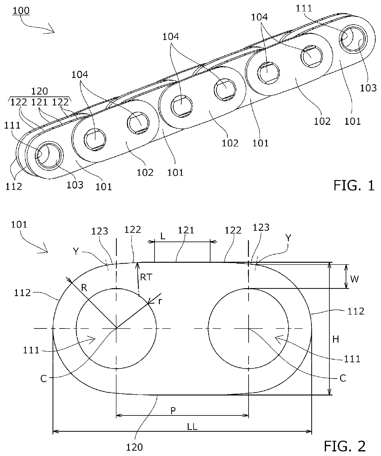
[0020]The chain 100 that uses an inner link plate 101 according to one embodiment of the present invention includes, as shown in FIG. 1, pairs of left and right inner link plates 101, cylindrical bushings 103 with their both ends press-fit in bushing holes 111 that are connection holes of the inner link plates 101, pairs of left and right outer link plates 102 disposed on both outer sides of the inner link plates 101, and connecting pins 104 rotatably inserted in the bushings 103 and having both ends press-fit in pin holes of the outer link plates 102. A large number of these inner link plates 101 and outer link plates 102 are alternately coupled together by the connecting pins 104 along the longitudinal direction of the chain.

[0021]The inner link plate 101 is vertically and horizontally symmetrical as shown in FIG. 1 and FIG. 2. A guide-side end surface 120 is made up of a flat portion 121 formed by a flat surface parallel to a line connecting centers of connection holes 111 at lea...


PUM


Abstract

To provide a versatile and easy-to-produce link plate that can reduce frictional resistance and keep surface pressure low while maintaining a small height of a guide-side end surface, and can secure a tensile strength, and a chain. The guide-side end surface of the link plate is made up of a flat portion formed by a flat surface parallel to a line connecting centers of connection holes at leading and trailing ends, and both end surface portions on both ends in the chain longitudinal direction of the flat portion. The both end surface portions are formed to come closer to the line connecting the centers of the leading-end and trailing-end connection holes as the both end surface portions extend further from the flat portion.

Description

BACKGROUND OF THE INVENTION1. Field of the Invention[0001]The present invention relates to a link plate having connection holes at leading and trailing ends, a sliding contact part that makes sliding contact with a guide member, and a guide-side end surface in an area between centers of the leading-end and trailing-end connection holes along a chain longitudinal direction on one side where the link plate has the sliding contact part.2. Description of the Related Art[0002]Link plates, which have connection holes at leading and trailing ends and sliding contact parts that make sliding contact with guide members, of roller chains, bushing chains, silent chains and the like used in power transmission mechanisms of automobiles, industrial machines and the like have been known.[0003]Link plates of a common chain have a guide-side end surface that is entirely flat in the area between the centers of leading-end and trailing-end connection holes along the longitudinal direction of the chain ...

Claims


Application Information

Patent Timeline
Patent Type & Authority Patents(United States)
IPC IPC(8): F16G15/12
CPCF16G15/12F16G13/06F16G13/02
Inventor KOYAMA, MASAHIRO
Owner TSUBAKIMOTO CHAIN CO
Why Eureka
Try Eureka