Apparatus and method for three-dimensional printing

a three-dimensional printing and apparatus technology, applied in the field of printing apparatuses, can solve the problems of damage to the workpiece, deformation of the release layer, and difficulty in separating the workpiece from the release layer, and achieve the effect of facilitating the separation of workpieces

Active Publication Date: 2022-11-15
YOUNG OPTICS
View PDF7 Cites 0 Cited by
  • Summary
  • Abstract
  • Description
  • Claims
  • Application Information

AI Technical Summary

Benefits of technology

[0004]An embodiment of the present invention provides a three-dimensional printing apparatus for facilitating the separation of workpieces from the release layer.
[0006]An embodiment of the present invention utilizes the fluid passage(s) disposed on the plate or the lifting device(s) for lifting the release layer to balance the pressure along the two sides of the release layer, thus eliminating the low-pressure vacuum built between the release layer and the plate. An embodiment of the present invention facilitates the separation of workpieces from the release layer, avoiding workpiece damages and release layer deformation, as well as improving the speed and stability of three-dimensional printing.

Problems solved by technology

However, in conventional three-dimensional printing devices, the space between the release layer and the plate becomes airtight during printing of a workpiece and low-pressure vacuum builds up therewithin during releasing of the resulting workpiece, therefore causing difficulties in separating the workpiece from the release layer.
While increasing the uplift force may be helpful in separating the workpiece from the release layer, application of strong uplift forces often leads to damage of the workpiece and deformation of the release layer.

Method used


Image

  • Apparatus and method for three-dimensional printing
  • Apparatus and method for three-dimensional printing
  • Apparatus and method for three-dimensional printing

Examples


Embodiment Construction

[0016]The present invention will now be described more specifically with reference to the following embodiments. It is to be noted that the following descriptions of preferred embodiments of this invention are presented herein for purpose of illustration and description only. It is not intended to be exhaustive or to be limited to the precise form disclosed.

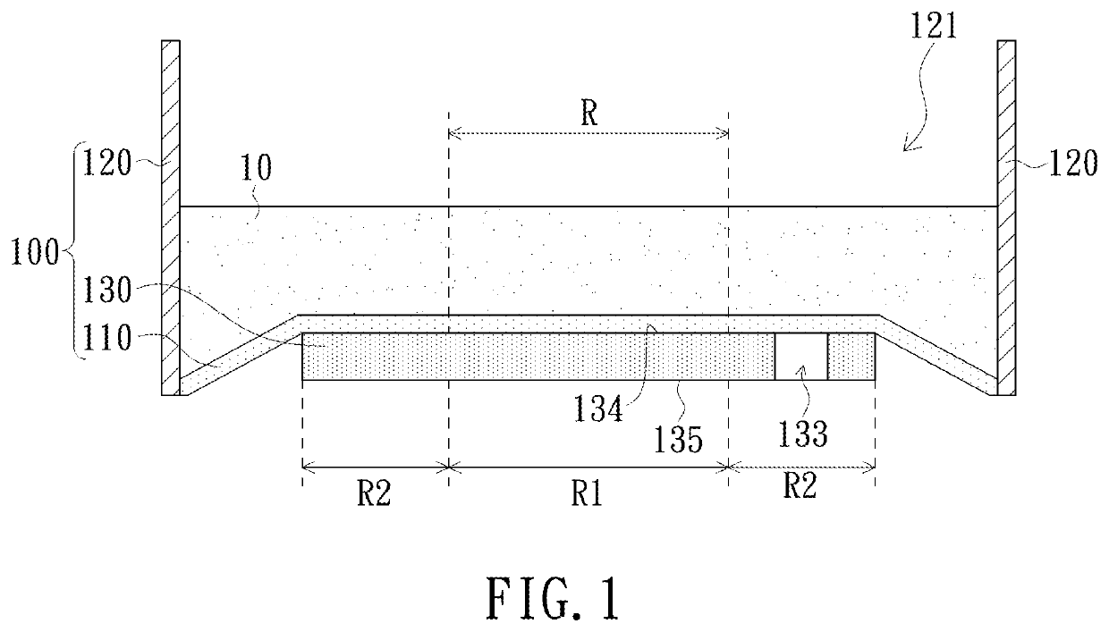
[0017]Referring now to FIG. 1. A liquid tank 100 of the present embodiment is applicable to a three-dimensional printing apparatus, and is configured to accommodate a photosensitive liquid 10. The liquid tank 100 includes a release layer 110 and a plate 130. The release layer has a workpiece curing area R, onto which an curing light beam provided by the three-dimensional printing apparatus irradiates. The plate 130 supports the release layer 110, and has a first area R1 corresponding to the workpiece curing area R and a second area R2 adjacent to the first area R1. The second area R2 has at least one fluid passage 133 extending f...


PUM

PropertyMeasurementUnit
photosensitiveaaaaaaaaaa
flexibleaaaaaaaaaa
areaaaaaaaaaaa

Abstract

A three-dimensional printing apparatus includes a liquid tank. The liquid tank includes a release layer and a plate. The release layer has a workpiece curing area, and the plate supports the release layer and has a first area corresponding to the workpiece curing area and a second area adjacent to the first area; the second area has at least one fluid passage extending from a first surface of the plate contacting the release layer to a second surface of the plate. The embodiments of the present invention facilitate the separation of workpieces from the release layer. Another three-dimensional printing apparatus and a three-dimensional printing method are also provided.

Description

FIELD OF THE INVENTION[0001]The present invention relates to a printing apparatus, and more particularly to an apparatus and method for three-dimensional printing.BACKGROUND OF THE INVENTION[0002]In conventional light curing three-dimensional printing devices, a release layer and a plate for supporting the release layer are disposed on the bottom of a tank for accommodating photosensitive resins. In printing of a workpiece, the photosensitive resins would be cured to form a layer of the workpiece and attach to the release layer. To initiate printing of the following layer, applying a force to lift up the workpiece is required to separate the workpiece from the release layer and allow uncured photosensitive resins to fill between the workpiece and the release layer. However, in conventional three-dimensional printing devices, the space between the release layer and the plate becomes airtight during printing of a workpiece and low-pressure vacuum builds up therewithin during releasing...

Claims


Application Information

Patent Timeline
Patent Type & Authority Patents(United States)
IPC IPC(8): B29C64/124B33Y10/00B33Y30/00B29C64/255B29C33/68B29K483/00B29K427/18
CPCB29C64/124B29C33/68B29C64/255B33Y10/00B33Y30/00B29K2427/18B29K2483/00B29K2995/0018B29K2995/0026
Inventor WU, LI-HAN
Owner YOUNG OPTICS
Why Eureka
Try Eureka