

Diffusing adhesive layer, optical member and liquid-crystal display device
a technology of optical components and adhesive layers, applied in the direction of diffusing elements, instruments, optics, etc., can solve the problems of hardly keeping the balance between light transmittance and diffusing characteristics
Inactive Publication Date: 2001-05-31
NITTO DENKO CORP
View PDF0 Cites 19 Cited by
- Summary
- Abstract
- Description
- Claims
- Application Information
AI Technical Summary
Problems solved by technology
Hence, there was a problem that the balance between light transmittance and diffusing characteristic was hardly kept.
Method used
View moreImage
Smart ImageViewing Examples

Examples
example 2
[0047] A diffusing adhesive layer was obtained in the same manner as in Example 1 except for that in which 33% by weight of the colorless particles were dispersively contained in a transparent acrylic adhesive layer.
Login to View More PUM
| Property | Measurement | Unit |
|---|---|---|
| mean particle size | aaaaa | aaaaa |
| thickness | aaaaa | aaaaa |
| thickness | aaaaa | aaaaa |
Abstract
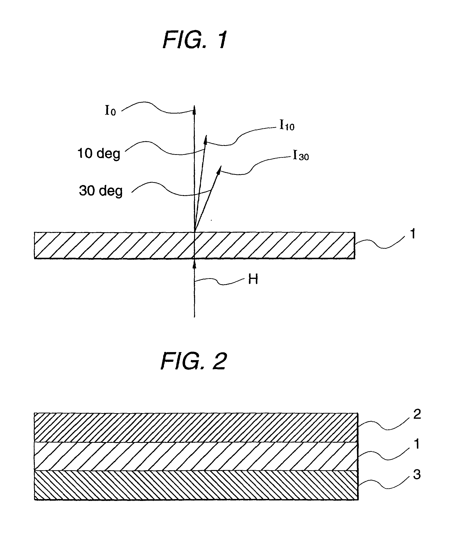
A diffusing adhesive layer has a light-transmissible adhesive layer dispersively containing colorless light-transmissible particles so as to exhibit light diffusing characteristic. The light diffusing characteristic of the diffusing adhesive layer is not higher than 10% in terms of a light diffusion factor which is defined as 100xI30 / I10 when I30 is the intensity of light transmitted in a direction inclined by 30 degrees relative to a direction of perpendicular transmission of perpendicularly incident light, and I10 is the intensity of light transmitted in a direction inclined by 10 degrees relative to the direction of perpendicular transmission of perpendicularly incident light. Another diffusing adhesive layer has a total light transmission factor of not lower than 85% and a direct transmission factor of not higher than 30%. In an optical member, one of the diffusing adhesive layers is provided on an optical material having at least a polarizing plate or a retarder plate. In a reflection type liquid-crystal display device, the optical member and one of the diffusing adhesive layers are provided between a liquid-crystal cell and a polarizing plate.
Description
[0001] 1. Field of the Invention[0002] The present invention relates to a diffusing adhesive layer excellent in balance between light transmittance and diffusing characteristic and adapted for formation of a liquid-crystal display device excellent in visibility such as brightness, and an optical member using the diffusing adhesive layer.[0003] The present application is based on Japanese Patent Applications No. Hei. 11-159663 and 159664, which are incorporated herein by reference.[0004] 2. Description of the Related Art[0005] Heretofore known was a light diffusion type adhesive layer which was configured to contain particles having refractive indices different from one another to thereby have light diffusing characteristic so that a viewing angle for liquid-crystal display could be enlarged. However, if the diffusing characteristic was improved to attain the enlargement of the viewing angle while self-adhesive applicability excellent in reliability was satisfied, the transmittance d...
Claims
Login to View More Application Information
Patent Timeline
 Patent Type & AuthorityApplications(United States)
IPC IPC(8): G02F1/1335G02B5/02
CPCG02B5/0242G02B5/0278G02F1/133504G02F1/1335
InventorYANO, SHUUJI
OwnerNITTO DENKO CORP