

Lens, manufacturing method thereof, and optical device using the same lens
a manufacturing method and lens technology, applied in the field of optical lenses, can solve the problems of increasing difficulty in inspecting the lens, poor workability, and recent size reduction
- Summary
- Abstract
- Description
- Claims
- Application Information
AI Technical Summary
Benefits of technology
Problems solved by technology
Method used
Image

Examples
first embodiment
[0108] (First Embodiment)
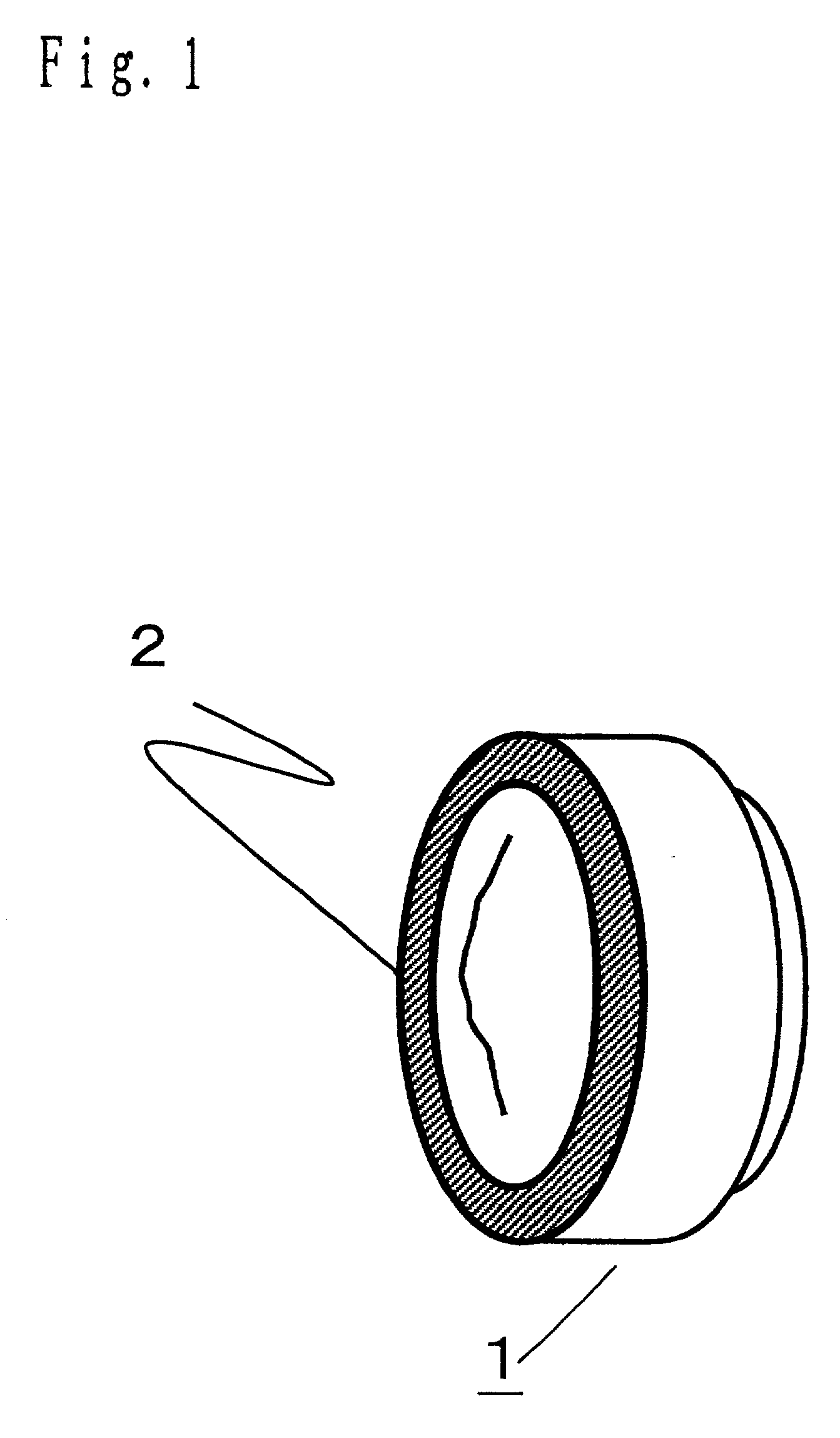
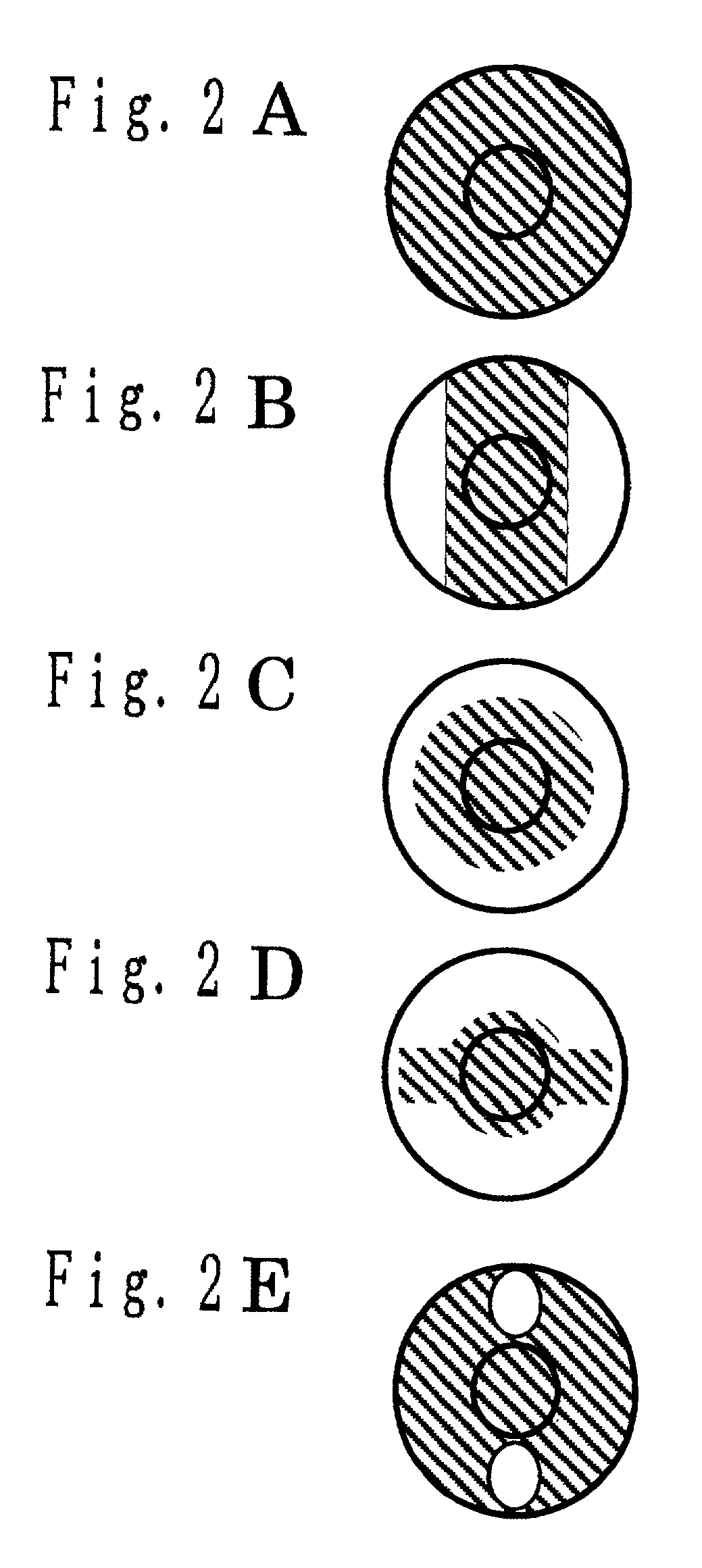
[0109] First, the following will discuss the configuration of an optical lens according to a first embodiment of the present invention. FIG. 1 shows the optical lens of the first embodiment according to the present invention. As shown in FIG. 1, a marking 2 is formed on a surface of an optical lens 1. Any pattern is applicable as the marking 2 as long as it is simply distinguishable. The examples of the pattern are shown in FIGS. 2B to 2E. A white background other than diagonal lines is a marking. As shown in FIGS. 2B to 2E, a marking is formed entirely or partially outside an effective area of the lens to distinguish between the surfaces of the lens. In this case, any marking is applicable as long as the surface and the back can be distinguished from each other. Further, the optical lens 1 is, for example, 2 millimeters or smaller in size. Moreover, although the present embodiment does not specify the kind of the optical lens 1, the optical lens 1 is a coup...
second embodiment
[0124] (Second Embodiment)
[0125] First, referring to FIGS. 9 and 10, the configuration of a lens 101 will be discussed according to a second embodiment. Here, FIG. 9 is a plan view showing the lens 101, and FIG. 10 is a sectional view taken along A-A' line of the lens 101 shown in FIG. 9.
[0126] The lens 101 has an effective area for transmitting light and an outer region of the effective area. The surface of the outer region is visually distinguishable from that of the inner region. Here, the lens 101 has a size of, for example, 2 millimeters or smaller.
[0127] As described above, on both surfaces of the lens 101, the outer regions of the effective area are subjected to surface treatment for visual discrimination so as to form a discrimination part 102.
[0128] In order to provide lenses with a preferable yield, it has been conventionally considered that flaws and dust adhered to a region outside the effective area are not tolerable, even though the region is not fundamentally used. Ho...
third embodiment
[0130] (Third Embodiment)
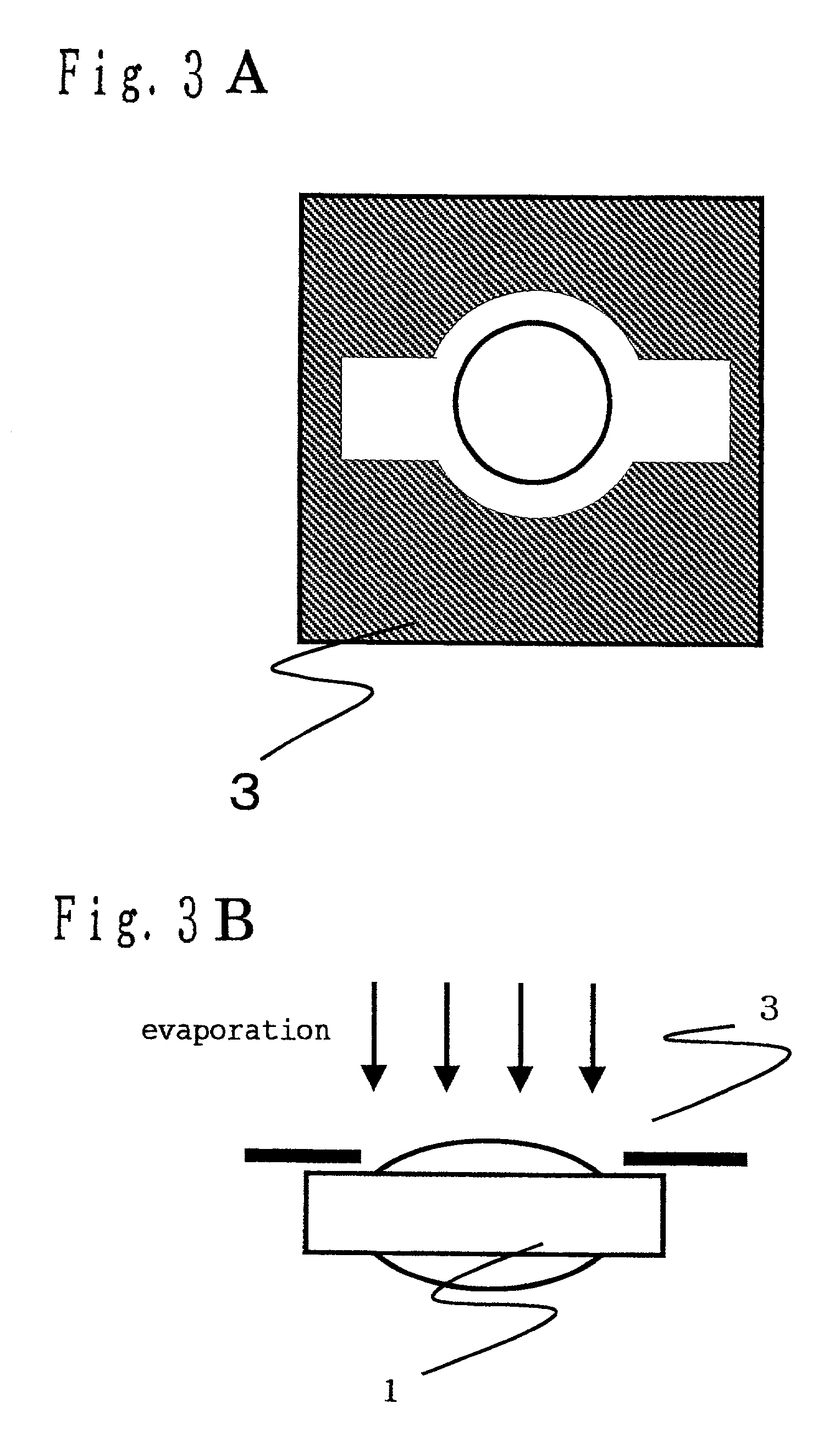
[0131] Mainly referring to FIGS. 11 and 12, the configuration and operation of a lens manufacturing device will be described according to the present embodiment. Here, the following will discuss an embodiment of a lens manufacturing method according to the present invention as well as the configuration and operation of the lens manufacturing device according to the present embodiment.
[0132] The lens manufacturing device of the present embodiment is provided with means of evaporating a coating for visual discrimination between a surface inside an effective area and a surface outside the effective area of a lens 101'.
[0133] While discussing the operation of the above-mentioned lens manufacturing device, the following will describe an embodiment of the lens manufacturing method for each of (1) a molding step and (2) an evaporating step.
[0134] (1) molding step; as shown in FIG. 12 which is an explanatory drawing showing the molding step, a lens transparent mater...
PUM
| Property | Measurement | Unit |
|---|---|---|
| Area | aaaaa | aaaaa |
Abstract
Description
Claims
Application Information