Color image forming apparatus

a color image and forming apparatus technology, applied in the field of can solve the problems of inconvenient high-speed operation of the rotary color image forming apparatus, inconvenient use of the electrographic process apparatus, and insufficient protection from the effects of printing fog

Inactive Publication Date: 2001-10-11
BROTHER KOGYO KK
View PDF0 Cites 7 Cited by
  • Summary
  • Abstract
  • Description
  • Claims
  • Application Information

AI Technical Summary

Benefits of technology

0037] The developer of the present invention may include a charge control agent made of styrene-acr

Problems solved by technology

Since the switching speed of the developing unit is limited, the rotary color image forming apparatus is not suitable for high-speed operation.
However, it takes too much time and trouble to apply the double photosensitive layer to a photosensitive belt, which has a large area.
Moreover, the inner charge generation layer is very thin.
Consequently, if the conductive base sheet has an even slight surface asperity, it is not possible to form a good charge generation layer on the sheet.
This lowers the yield of the product.
There is a structural limitation that, in order to form a positively chargeable double-

Method used


Image

  • Color image forming apparatus
  • Color image forming apparatus
  • Color image forming apparatus

Examples


Embodiment Construction

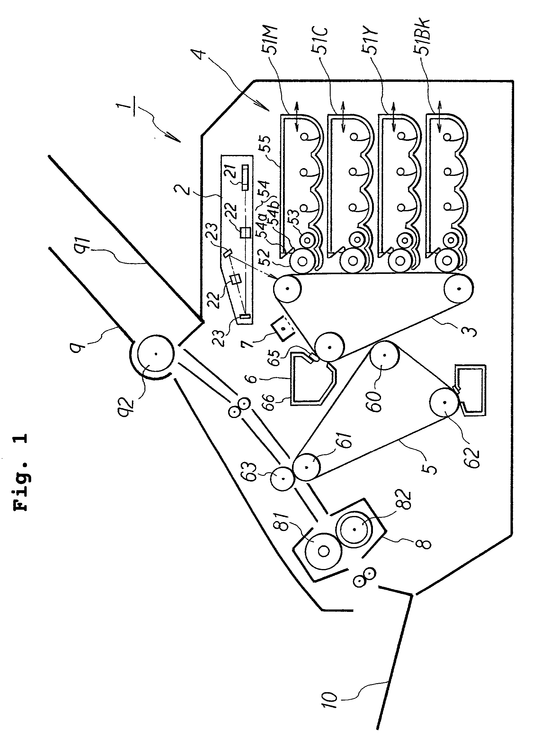
[0044] With reference to FIG. 1, a color laser printer 1 as a color image forming apparatus includes a scanning unit 2 as an exposure unit, a photosensitive belt 3, a developing unit 4 including four developing devices, an intermediate transfer belt 5, a cleaner 6, a charger 7, a fixing unit 8, a paper feed unit 9 and a paper discharge tray 10.

[0045] The scanning unit 2 includes a laser light source (not shown), a polygonal mirror 21, a lens 22 and mirrors 23, and irradiates the outer side of the photosensitive belt 3 with laser beams based on image data.

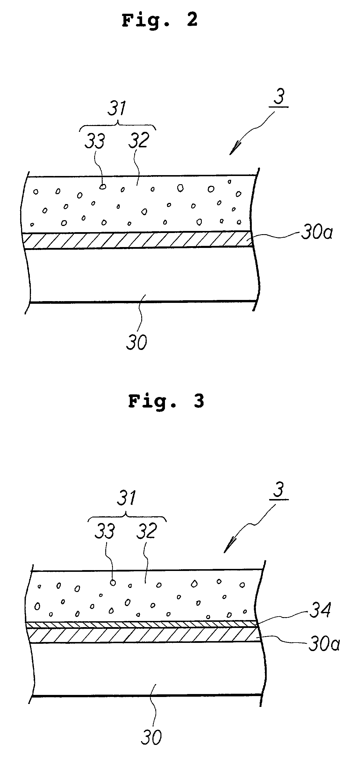
[0046] As shown in FIG. 2, the photosensitive belt 3 may, as an example, consist of a base sheet 30 and a photosensitive layer 31. The base sheet 30 may be a PET film with an aluminum vapor-deposited film 30a formed as a conducting layer on one side. The photosensitive layer 31 is a single layer for positive electrification or charging, which is formed on the aluminum film 30a. The photosensitive layer 31 is a charge transport layer...


PUM

PropertyMeasurementUnit
Particle diameteraaaaaaaaaa
Thicknessaaaaaaaaaa

Abstract

A color image forming apparatus includes a photosensitive belt, which consists of a resinous base sheet and an organic photosensitive layer formed thereon. The photosensitive layer consists of a charge transport layer and charge generation particles dispersed therein. The image forming apparatus ensures good color image quality even if the developer used for this former is toner made of styrene-acrylic resin. The image forming apparatus also includes developing rollers in contact with the photosensitive belt. Suitable shearing force can be applied to the toner if the speed ratio of the developing rollers to the photosensitive belt ranges from 1.3 to 2.0. The developer includes an external additive which has a particle diameter of 30 or more nm. The external additive can effectively prevent printed sheets from halation.

Description

FIELD OF THE INVENTION[0001] The present invention relates to an image forming apparatus for forming an image with an electrified non-magnetic single-component developer. In particular, the invention relates to a color image forming apparatus that performs development with a non-magnetic single-component developer in contact with a photosensitive belt including a photosensitive layer and charge generators dispersed in the layer.DESCRIPTION OF THE RELATED ART[0002] A conventionally known image forming apparatus includes a photosensitive drum or another electrostatic latent image carrier, on which an electrostatic latent image can be formed. The image forming apparatus also includes a developing unit for conveying toner or other developer onto the latent image carrier to develop the latent image. The image forming apparatus further includes a supplying unit for supplying developer to the developing unit.[0003] A rotary color image forming apparatus of this type includes four developin...

Claims


Application Information

Patent Timeline
IPC IPC(8): G03G9/08G03G5/04G03G5/06G03G5/10G03G9/087G03G13/01G03G15/01G03G15/08
CPCG03G5/04G03G5/06G03G9/08711G03G13/013G03G2215/0174G03G13/0133
Inventor SATO, SHOUGO
Owner BROTHER KOGYO KK
Why Eureka
Try Eureka