
Polishing pad release liner system

a technology of release liner and polishing pad, which is applied in the direction of lapping tools, metal-working equipment, manufacturing tools, etc., can solve the problems of increasing the chance of the operator either damaging the polishing pad or injuring himself/herself, and reducing the operational life of the polishing pad, so as to achieve easy and safe removal, easy removal, and easy removal

Inactive Publication Date: 2001-11-08
RODEL HLDG INC
View PDF2 Cites 9 Cited by
  • Summary
  • Abstract
  • Description
  • Claims
  • Application Information

AI Technical Summary

Benefits of technology

[0009] It is a further object of the present invention to provide a release liner for a polishing pad that is easier and safer to remove.
[0010] It is a further object of the present invention to provide a polishing pad release liner that is easier to remove without damaging the polishing pad.
[0011] It is a further object of the present invention to provide a polishing pad release liner that can be easily removed while wearing gloves.
[0012] It is a further object of the present invention to provide a polishing pad which can be manufactured without special cutting dies.
[0014] It is a further object of the present invention to provide a polishing pad that includes cost effective features for aiding in the removal of a release liner.
[0018] The resulting pull tab enables an operator to quickly remove the release liner from the polishing pad safely and without damaging the polishing pad. In addition such an exemplary pull tab can be provided, without significantly increasing the cost and complexity of manufacturing polishing pads.

Problems solved by technology

Unfortunately, operators of polishing fixtures typically wear cumbersome rubber gloves which make removal of the release liner from the polishing pad very difficult.
Using a knife increases the opportunity for the operator to either damage the polishing pad or injure himself / herself.
Also, folding the pad may cause a crease which can significantly decrease the pad's operational lifetime.
Unfortunately, to manufacture a polishing pad with a release liner that is a different shape than the underlying polishing pad, special cutting dies are required.
These prior art features significantly increase the complexity and cost of manufacturing and mounting polishing pads.

Method used


Image

  • Polishing pad release liner system
  • Polishing pad release liner system

Examples


Embodiment Construction

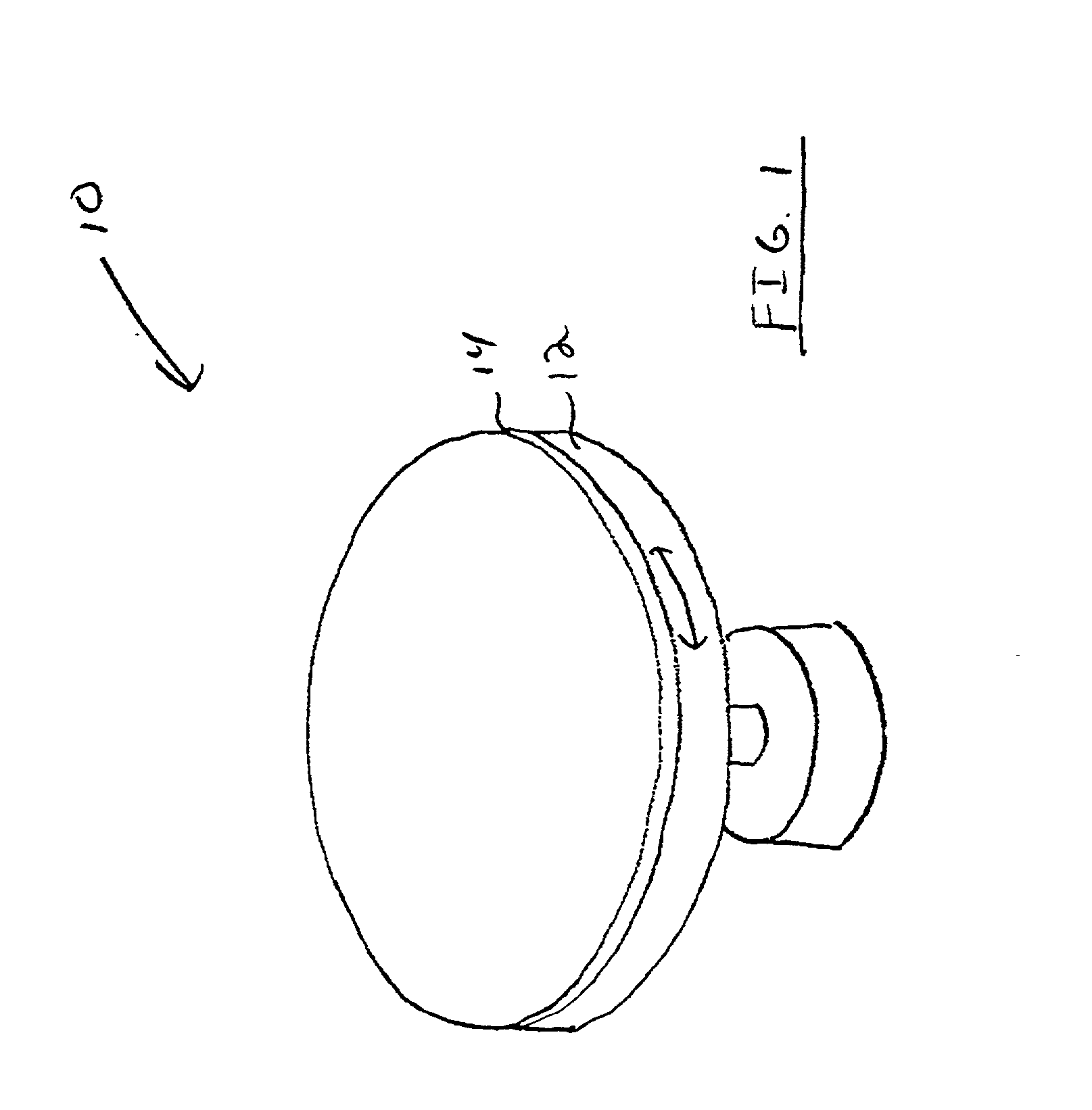
[0023] Referring now to the drawings and particularly to FIG. 1, there is shown therein a perspective view representative of an exemplary polishing fixture 1 0. The polishing fixture 10 includes a disk 12 that is operative to rotate. Mounted to the disk 12 is a polishing pad 14. When a semiconductor wafer is placed adjacent the polishing pad, the relative movement between surfaces of the pad and the wafer facilitates polishing and planarizing of the wafer.

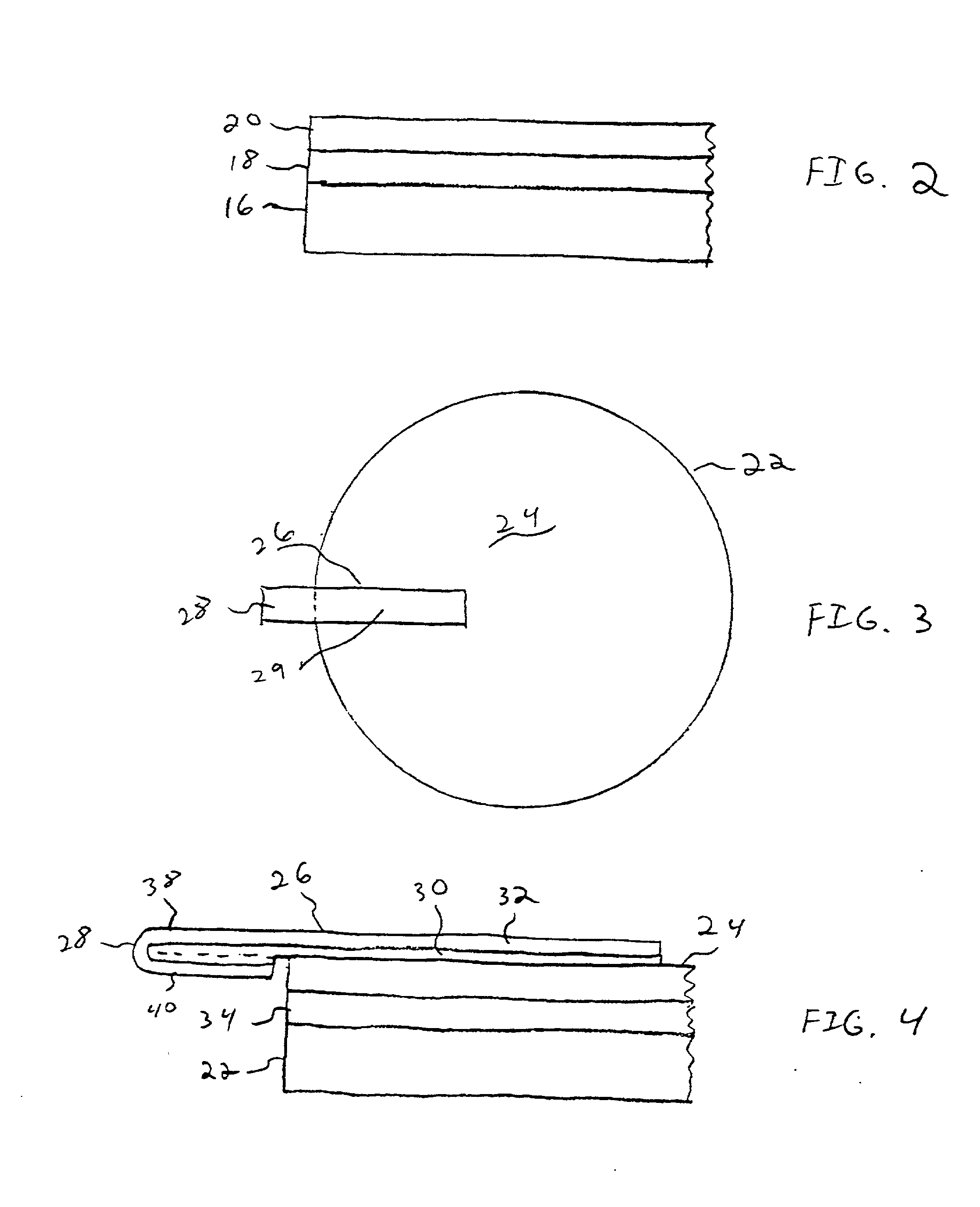
[0024] FIG. 2 shows an exemplary prior art polishing pad 16 prior to being mounted to a polishing fixture. The polishing pad 16 is manufactured with an adhesive layer 18 which facilitates adhesion of the pad 16 to a polishing fixture. However to prevent contamination of the adhesive layer 18 during shipment and storage, the polishing pad 16 is manufactured with a protective release liner 20 over the adhesive layer 18. The protective release liner 20 is typically comprised of a flexible plastic sheet that is operative to peel away f...


PUM


Abstract

A polishing pad for planarizing and polishing a semiconductor substrate. The polishing pad (22) includes an adhesive layer (34) that is operative to adhere the polishing pad to a polishing fixture. To protect the adhesive layer from contamination during storage and shipment, a release liner (24) is placed over the adhesive layer. The release liner has sufficient surface characteristics to stay in adhesive connection with the adhesive layer during storage and shipment; however, the release liner is operative to be peeled away from the adhesive layer without disturbing the bond between the polishing pad and the adhesive layer. To aid in the removal of the release liner from the polishing pad, the release liner includes a pull tab (26). The pull tab is comprised of a single-sided tape that is adhered to the outer surface of the release liner. A portion (28) of the pull tab extends beyond the edge of the release liner. This extending portion has sufficient length to enable an operator of the polishing fixture to remove the release liner from the polishing pad while wearing gloves.

Description

[0001] This application claims the benefit of U.S. Provisional Patent Application Serial No. 60 / 201,634 filed May 3, 2000.[0002] This invention relates to chemical mechanical polishing systems. Specifically this invention relates to features of a polishing pad for facilitating easier removal of a release liner.[0003] Integrated circuits are typically fabricated from semiconductor wafers. The surfaces of semiconductor wafers are finely polished and planarized using chemical mechanical polishing (CMP) processes. Many of these polishing processes use a polishing fixture that includes a revolving belt or disc. The belt or disk of a polishing fixture is operative to accept one or more polishing pads that are adhered to the outer surfaces of the belt or disc. When a substrate such as a semiconductor wafer is placed adjacent the moving belt or disc, the polishing pad is operative to polish and planarize the surface of the wafer.[0004] Polishing pads include an adhesive layer. The adhesive ...

Claims


Application Information

Patent Timeline
Patent Type & Authority Applications(United States)
IPC IPC(8): B24B37/20
CPCB24B37/20
Inventor FEELEY, GEORGE F.
Owner RODEL HLDG INC
Learn More