Injection device having an improved syringe cap removal

a technology of injection device and syringe cap, which is applied in the direction of intravenous device, other medical devices, infusion needles, etc., can solve the problems that the syringe cap must be easy to maneuver, and achieve the effect of convenient and safe removal by users

Active Publication Date: 2022-03-29
NEMERA LA VERPILLIERE SAS
View PDF11 Cites 0 Cited by
  • Summary
  • Abstract
  • Description
  • Claims
  • Application Information

AI Technical Summary

Benefits of technology

[0021]However, it is generally imposed that the force required in order to remove the protective cap from the needle should be relatively low so that the user can remove the cap easily.
[0024]The invention aims to provide an assistance device for assisting in the operation of an injection syringe fitted with a cap removal device that is easy to handle, in other words requiring only a limited force by a user to remove the cap.
[0035]Thanks to the invention therefore, the cap can be easily and safely removed by a user.

Problems solved by technology

However, the syringe must also be easy to maneuver since the patient performing the injection himself may be weakened or feel a certain degree of apprehension in performing the injection.

Method used


Image

  • Injection device having an improved syringe cap removal
  • Injection device having an improved syringe cap removal
  • Injection device having an improved syringe cap removal

Examples


first embodiment

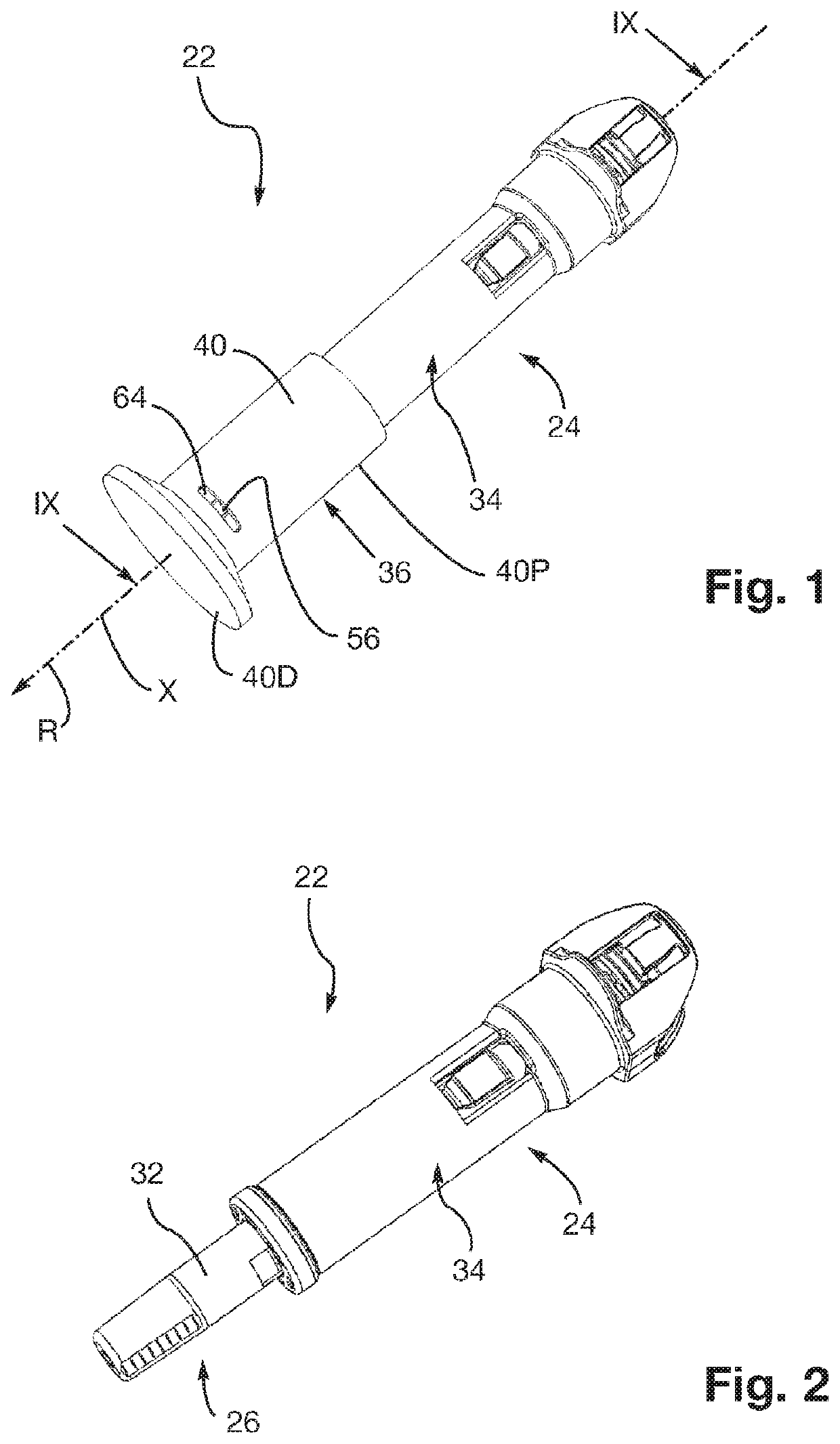
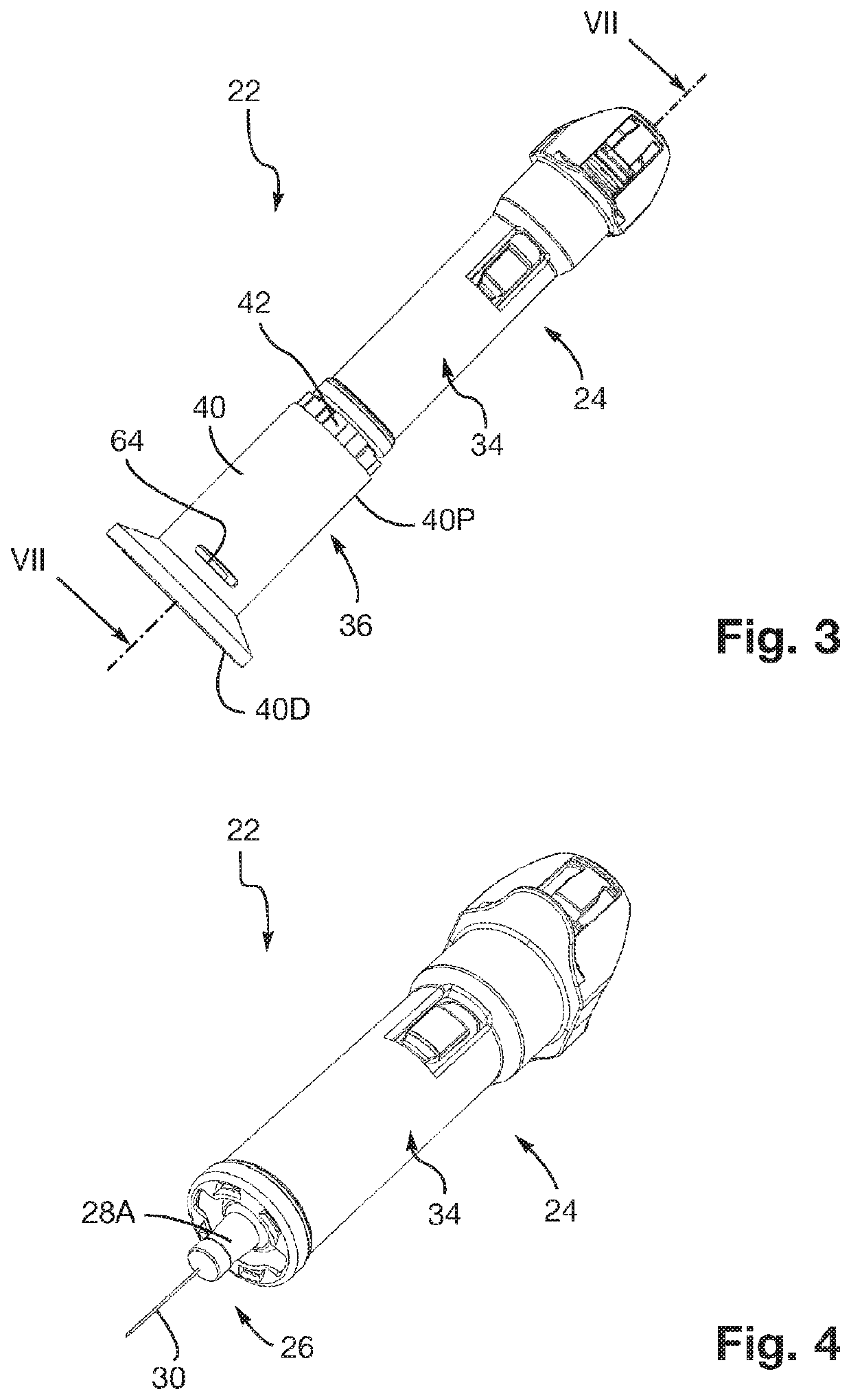
[0071]The injection assembly 22 comprises an assistance device 24 for assisting in the operation of an injection syringe according to the invention. The injection assembly 22 also comprises an injection syringe 26 (shown in particular on FIGS. 2, 4 and 7) housed in this assistance device 24.

[0072]In the example shown, the injection syringe 26 can be used to inject a liquid medication into the body of a patient.

[0073]As shown in particular on FIGS. 7 and 8, the injection syringe 26 comprises, traditionally, a syringe body 28 carrying an injection needle 30. Before using the injection assembly 22, the injection needle 30 is covered with a removable protective cap 32. This protective cap 32, covering the injection needle 30, is kept inserted on a complementary part 28A of the syringe body28, by friction.

[0074]The injection syringe 26 also comprises a piston (not shown) housed in the syringe body 28 and defining a chamber containing the medication to be injected. The piston is tradition...

second embodiment

[0116]We will now describe, referring to FIGS. 11 to 20, an injection assembly 22 comprising an assistance device for assisting in the operation of an injection syringe 26, according to the invention. As in the previous figures, the injection assembly 22 has a very general shape of revolution about the axis X.

[0117]On these FIGS. 11 to 20, the elements similar to those of the previous figures are designated by the same references.

[0118]The injection assembly 22 shown on FIGS. 11 to 20 comprises an injection syringe 26, shown in particular on FIGS. 16 to 20, similar to that described previously, housed in the assistance device 24 according to the second embodiment of the invention. FIG. 16 shows a rod 72 for maneuvering a piston 74. This piston 74, shown on FIGS. 17 to 20, is housed in the syringe body 28 so as to define the chamber 73 containing the medication to be injected.

[0119]Firstly, the assistance device 24 according to the second embodiment prevents or limits accidents when ...


PUM


Abstract

An assistance device for assisting in operation of an injection syringe including a syringe body carrying an injection needle covered with a protective cap. The assistance device includes a support for housing the syringe body, and a removal device for removing the protective cap, having a gripping member to be maneuvered by a user to remove this protective cap from the injection needle, and at least one extractor cooperating with the protective cap during removal of the protective cap. The removal device also has complementary members for controlling the extractor, which can be moved relative to each other in a relative engagement movement, to move the extractor between a reference configuration retracted relative to the protective cap and a cooperation configuration cooperating with the protective cap. The relative engagement movement is independent of the maneuvering movement applied by the user to the gripping member to remove the protective cap.

Description

FIELD OF THE INVENTION[0001]This invention relates to injection assemblies comprising an assistance device for assisting in the operation of an injection syringe and an injection syringe housed in this assistance device.BACKGROUND OF THE INVENTION[0002]In the medical field, for example, an injection syringe is used to inject a liquid medication into the body of a patient. The injection syringe generally comprises a syringe body carrying an injection needle, a piston housed in the syringe body defining a chamber containing the medication to be injected, and a rod for maneuvering this piston.[0003]Frequently, a third party injects the medication into the body of the patient using a syringe containing this medication.[0004]However, the possibility of the third party accidentally pricking himself with the syringe needle when handling the syringe must be avoided whenever possible.[0005]In the state of the art, for example in accordance with the description of WO 2015 / 044561, a first type...

Claims


Application Information

Patent Timeline
Patent Type & Authority Patents(United States)
IPC IPC(8): A61M5/32A61M5/20
CPCA61M5/3204A61M2005/2006A61M2205/586A61M5/20
Inventor DUGAND, PASCALSTAMP, KEVIN
Owner NEMERA LA VERPILLIERE SAS
Why Eureka
Try Eureka