Pressure tank valve socket

Inactive Publication Date: 2005-09-08
MCCARTHY DAVID
View PDF7 Cites 0 Cited by
  • Summary
  • Abstract
  • Description
  • Claims
  • Application Information

AI Technical Summary

Benefits of technology

[0012] One of the major objects of the pressure tank valve socket of the present invention is to provide a tool for easily and efficiently removing (or attaching) a valve from a pressure tank.
[0013] Another objective of th

Problems solved by technology

Because of the guard which surrounds the valve and because the valve is made of soft material; it is very difficult, if not imposs

Method used


Image

  • Pressure tank valve socket
  • Pressure tank valve socket
  • Pressure tank valve socket

Examples


Embodiment Construction

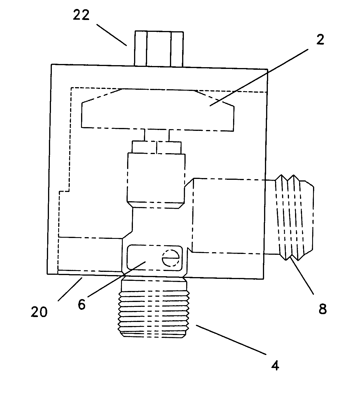
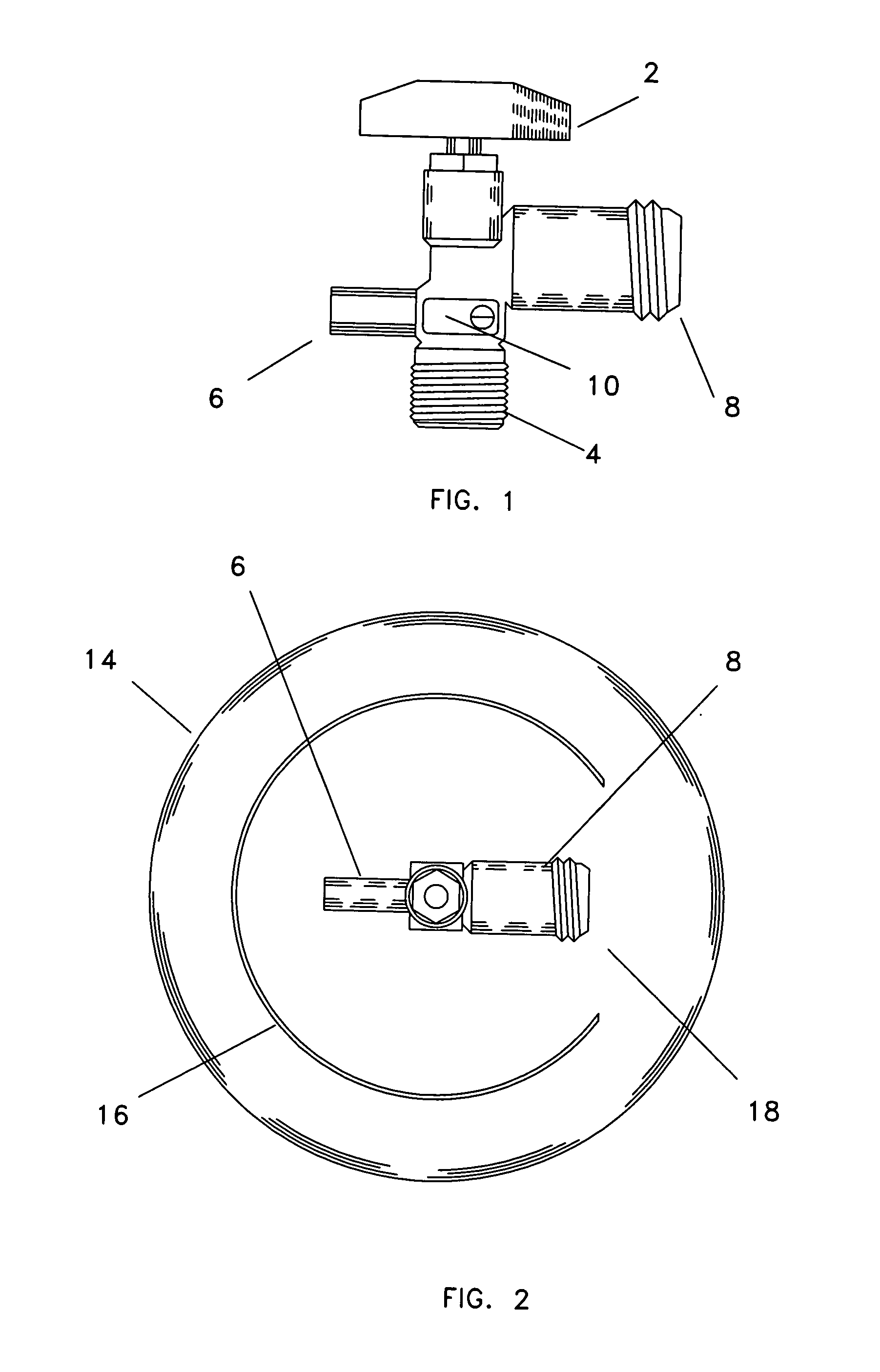
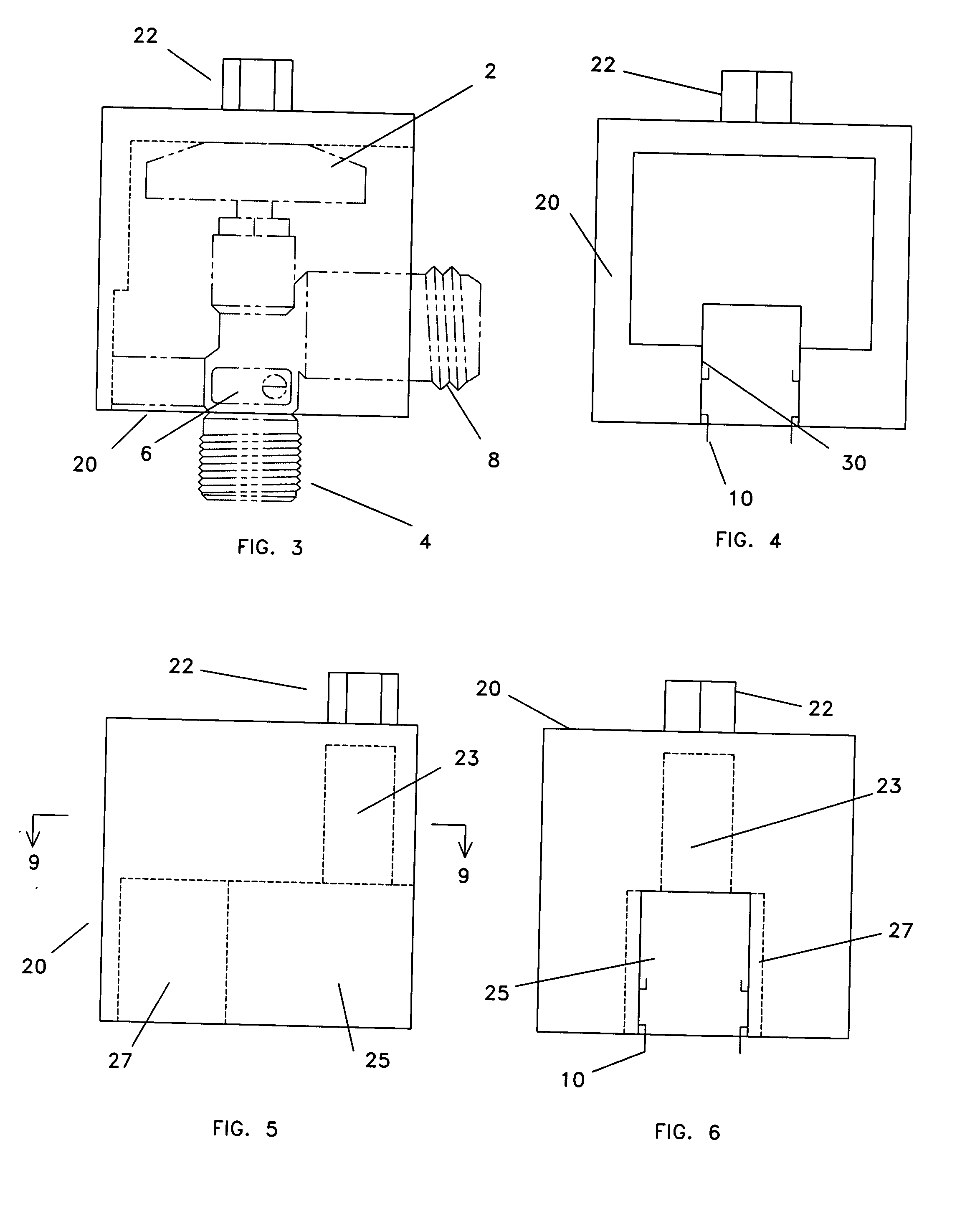
[0026] Referring to the drawings, FIGS. 1 through 10, there are shown three preferred forms of the pressure tank valve socket embodying the present invention. FIGS. 1 and 2 show a typical valve and propane tank. FIGS. 3 and 4 show an embodiment of the instant invention for use with valves having fixed handles; FIGS. 5 and 6 show an embodiment of the instant invention for use with valves having removable handles and external regulator connectors which are typically used with recreational vehicles; FIGS. 7 and 8 show an embodiment of the instant invention for use with valves having removable handles which are typically found in implements such as fork lifts; FIG. 9 is a sectional view of the socket shown in FIG. 5, and FIG. 10 is a sectional view of the socket shown in FIG. 7.

[0027] Now referring to FIG. 1, a typical propane valve is shown. For purposes of this application, the configuration of a common, barbecue grill, type propane tank and valve will be used for illustration. Again...


PUM

PropertyMeasurementUnit
Forceaaaaaaaaaa
Pressureaaaaaaaaaa

Abstract

Embodiments of a pressure tank valve socket are disclosed which may be used to safely remove the valve from a propane or other pressure tank without damaging the valve. The pressure tank valve socket applies force only to the sturdiest part of the valve and, thus, prevents injury to the more delicate parts of the valve.

Description

BACKGROUND OF THE INVENTION [0001] 1. Field of the Invention [0002] The present invention relates generally to tanks holding pressurized gasses such as propane and more specifically to tool for removing valves from such tanks. [0003] 2. Background Information [0004] All around the United States and throughout the world, hundreds of thousands of people use compressed gas stored in metal, usually steel, tanks. Perhaps the most common of these uses is the use of “bottled” propane in familiar steel tanks. Propane is used for a variety of purposes including barbecue grills, powering forklifts, and as a heating and cooking fuel for recreational vehicles. Although propane tanks are referenced in the following descriptions, the pressure tank valve socket of the instant invention could be easily adapted for use with a variety of pressure tank types. [0005] In the United States and in many other countries, the construction of propane tanks and valves and the filling of such tanks is highly re...

Claims


Application Information

Patent Timeline
IPC IPC(8): B25B13/00B25B13/06F16K31/32F16K51/00
CPCB25B13/00B25B13/06Y10T29/53596F16K51/00F16K31/32F17C13/04F17C2201/058F17C2205/0323F17C2205/0394F17C2209/22F17C2221/035F17C2223/0153F17C2270/0745Y10T137/6109
Inventor MCCARTHY, DAVID
Owner MCCARTHY DAVID
Why Eureka
Try Eureka