Method and system for reducing plasma loss in a magnetic mirror fusion reactor

a fusion reactor and magnetic mirror technology, applied in nuclear reactors, nuclear explosives, greenhouse gas reduction, etc., can solve the problems of ineffective multiple mirrors, inability to use, and plasma loss that needs to be addressed

Inactive Publication Date: 2001-11-22
NASA
View PDF0 Cites 8 Cited by
  • Summary
  • Abstract
  • Description
  • Claims
  • Application Information

AI Technical Summary

Problems solved by technology

Although the MMFR is considered promising as a main line fusion device, a problem that needs to be addressed is the loss of fusing plasma 20 through throat region 13.
However, increasing the field strength of mirror magnet 14 either increases stress on the existing magnet or requires the use of a larger and more expensive magnet, while the complexity and ineffectiveness of multiple mirrors makes their use unaccepta

Method used


Image

  • Method and system for reducing plasma loss in a magnetic mirror fusion reactor
  • Method and system for reducing plasma loss in a magnetic mirror fusion reactor

Examples


Embodiment Construction

)

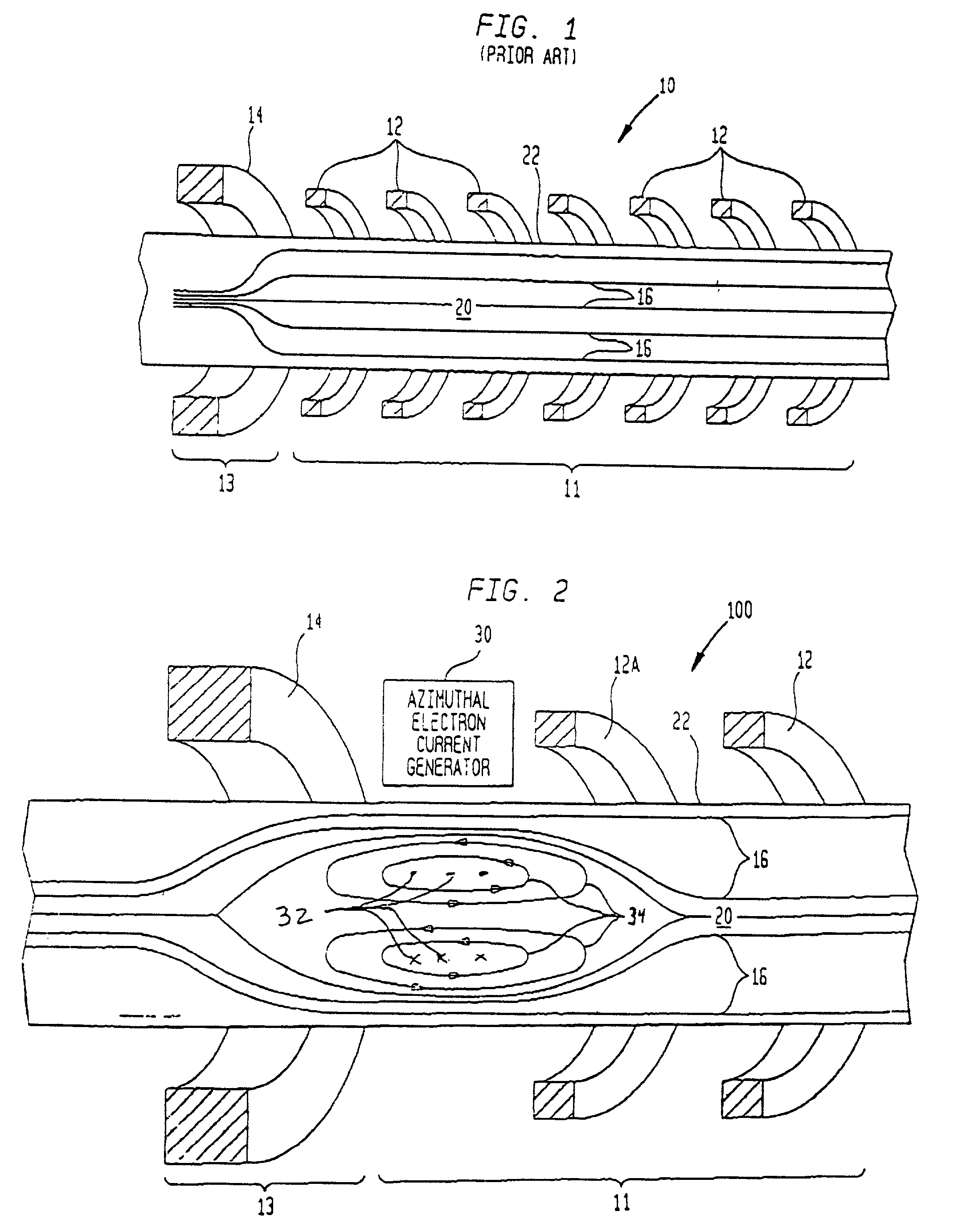
[0021] Referring again to the drawings, and more particularly to FIG. 2, a magnetic mirror fusion reactor (MMFR) modified in accordance with the present invention is illustrated and referenced generally by numeral 100. Common reference numerals are used for the elements that are the same as those described above with respect to the conventional MMFR 10 (FIG. 1). For purpose of description, only one end of MMFR 100 is illustrated. As would be understood by one of ordinary skill in the art, the other end of MMFR 100 (not shown) is a mirror image of the illustrated end.

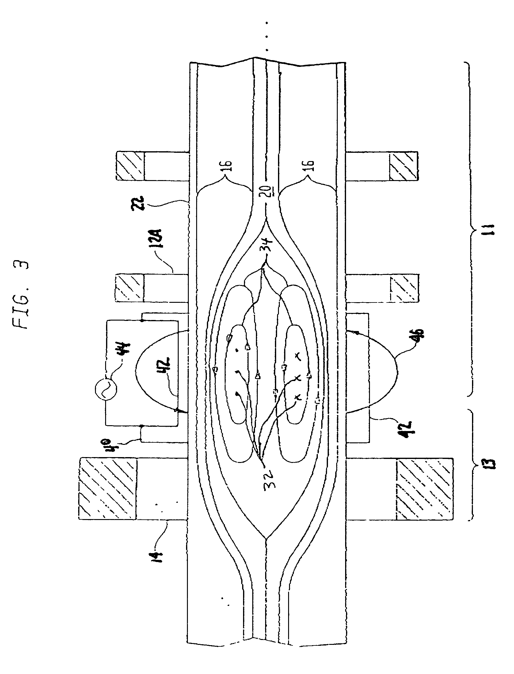
[0022] In the present invention, an azimuthal electron current generator 30 is disposed in the region between mirror magnet 14 and the nearest or adjacent main chamber magnet 12A of main chamber magnets 12. When activated, azimuthal electron current generator 30 causes a field reversed configuration to develop inside MMFR 100 and only between mirror magnet 14 and adjacent main chamber magnet 12A. Specifically, a plasma ...


PUM


Abstract

A method and system are provided for reducing plasma loss from the main chamber of a magnetic mirror fusion reactor (MMFR). The MMFR includes a mirror magnet defining a throat region and main chamber magnets defining a main chamber region adjacent the throat region. The present invention generates a field reversed configuration (FRC) inside the MMFR and only between the mirror magnet and the main chamber magnet that is adjacent to the mirror magnet.

Description

[0001] This is a continuation-in-part of co-pending application Ser. No. 09 / 334,411 filed Jun. 16, 1999.[0003] 1. Field of the Invention[0004] This invention relates to magnetic mirror fusion reactors. More specifically, the invention is a method and system for reducing plasma loss in a magnetic mirror fusion reactor by plugging the throat of the reactor.[0005] 2. Description of the Related Art[0006] One type of fusion reactor known in the art is a magnetic mirror fusion reactor (MMFR). As illustrated in FIG. 1, an MMFR 10 includes a main chamber region 11 defined by a plurality of main chamber magnets 12. Either end of MMFR 10, only one of which is illustrated in FIG. 1, has a throat region 13 defined by a mirror magnet 14. Magnetic field lines 16 generated in main chamber region 11 are constricted at throat region 13 by stronger magnetic field generated by mirror magnet 14. Note that main chamber magnets 12 and mirror magnet 14 are ring-shaped, but are shown cut away to clearly il...

Claims


Application Information

Patent Timeline
IPC IPC(8): H05H1/14
CPCG21B1/052H05H1/14Y02E30/122Y02E30/10
Inventor EMRICH, WILLIAM J. JR.
Owner NASA
Why Eureka
Try Eureka