
Speaker

a speaker and dynamic technology, applied in the field of dynamic speakers, can solve the problems of separating the diaphragm from the frame, ensuring the support structure is reliable, and increasing the possibility of diaphragm separation

Inactive Publication Date: 2001-11-29
STAR MICRONICS
View PDF0 Cites 2 Cited by
  • Summary
  • Abstract
  • Description
  • Claims
  • Application Information

AI Technical Summary

Benefits of technology

[0021] Since the diaphragm is clamped between the ring and the mounting portion which are caulked-jointed to each other, the supporting strength offered by the frame to the diaphragm is significantly increased as compared to the conventional technique attaching the diaphragm to the frame using only an adhesive. This reliably prevents the diaphragm from separating from the frame during the use of the speaker.
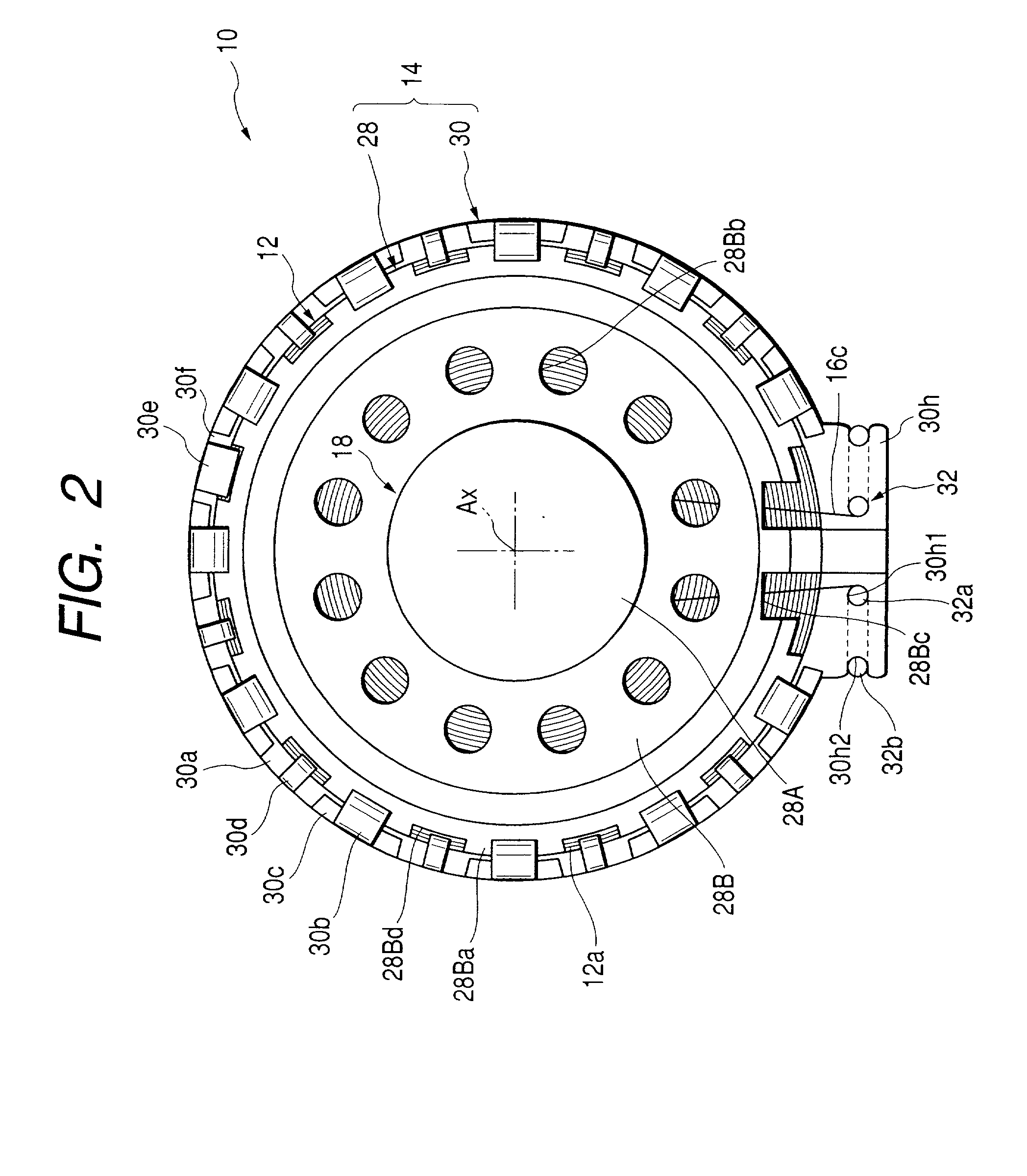
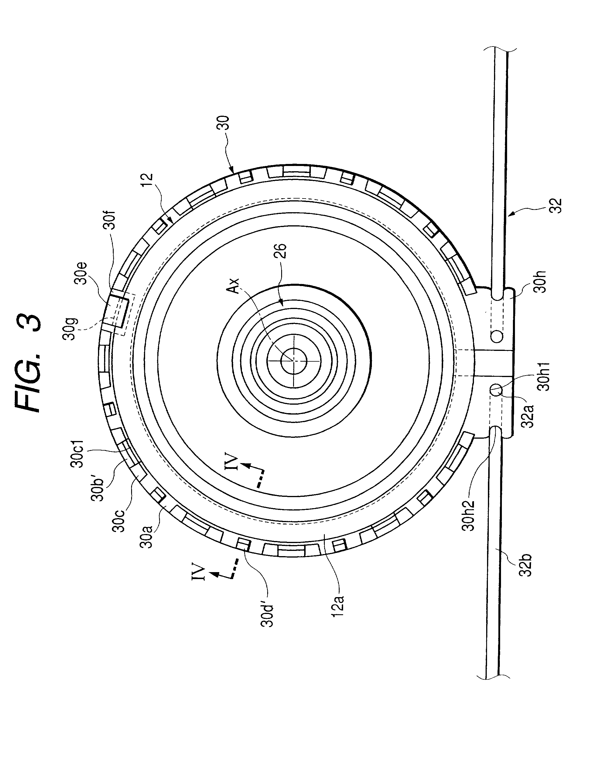
[0031] The mounting portion must be provided with openings for lead wires so that the lead wires of the voice coil that is attached to the diaphragm may be connected to the terminals. The caulked-joint of the ring and the mounting portion must be done at angular positions that are different from where the lead wires will be drawn out. If the afore-described circumferential direction positioning piece is formed to position the ring and the mounting portion in the circumferential direction, the caulked-joint of the two pieces can be reliably done at the prescribed angular positions. In particular, since, if the ring is caulked to the diaphragm in advance, the caulked-joint of the ring and the mounting portion must be done at angular positions that are different from where the ring is caulked to the diaphragm, the formation of the afore-described circumferential direction locating piece is particularly effective.

Problems solved by technology

However, simply adhereing and fixing the diaphragm to the frame does not provide the sufficiently reliable support structure for the diaphragm, and risk remains of the diaphragm separating from the frame during the use of the speaker.
This is particularly true when the speaker is mounted in an automobile, etc. where the speaker is subject to much shock and impact load that makes the separation of the diaphragm even more likely.
Furthermore, since the speaker with the diaphragm that is attached to the frame with the adhesive requires application of the adhesive during manufacturing, the automation of the speaker manufacturing process is made difficult and is further complicated by adjusting the viscosity of the adhesives and implementing the drying process following the application of the adhesives.

Method used


Image

  • Speaker
  • Speaker
  • Speaker

Examples


Embodiment Construction

[0042] The present invention will be described below in detail with reference to the accompanying drawings.

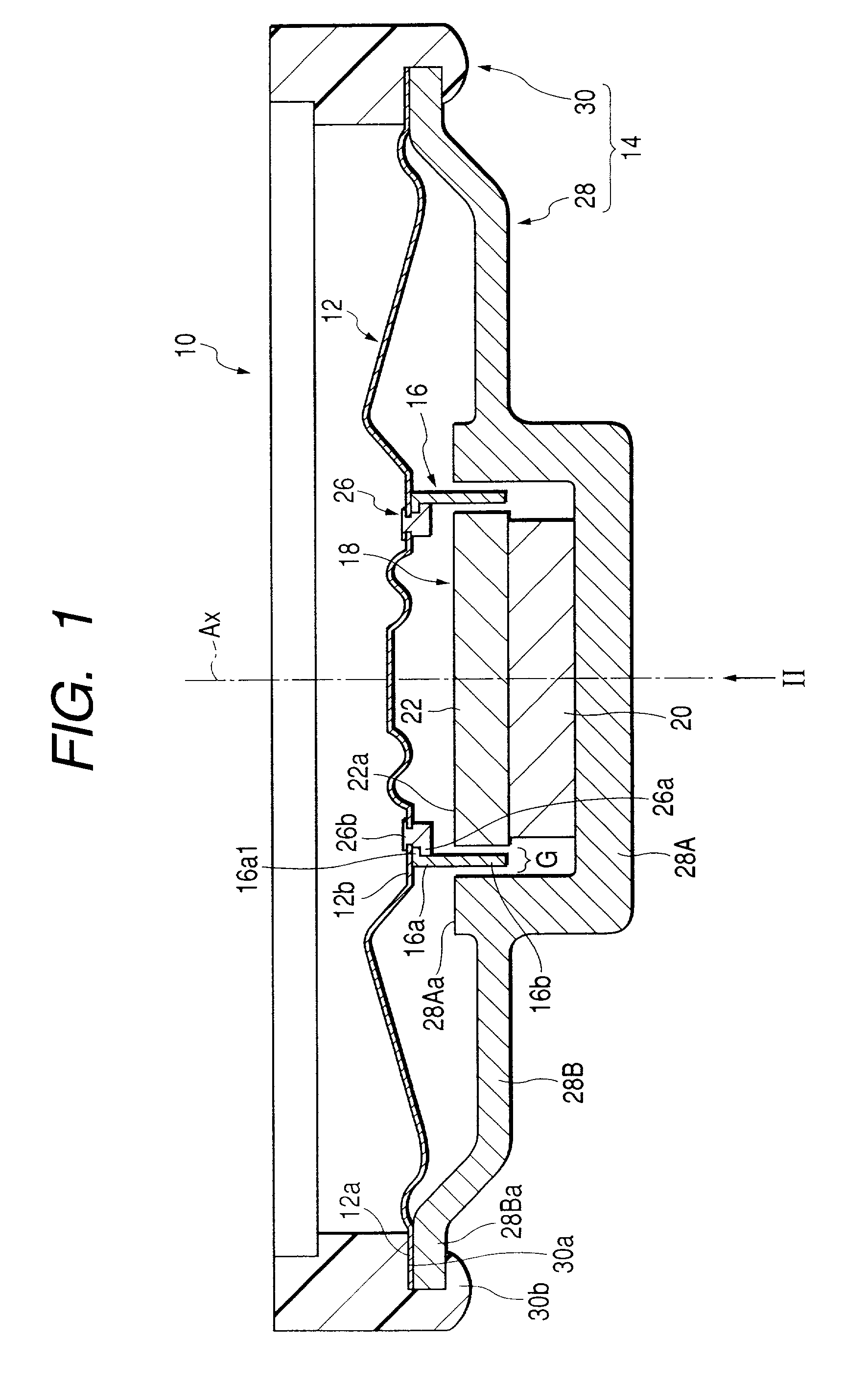
[0043] FIG. 1 is a side sectional view showing a speaker 10 according to an embodiment of the invention, in which the speaker faces upward. FIG. 2 is a view seen from the direction of arrow II.

[0044] As shown in FIG. 1, the speaker 10 according to the embodiment is a dynamic speaker comprising a diaphragm 12, a frame 14, a voice coil 16 and a magnetic circuit unit 18. This speaker 10 is a small-sized speaker having an outer diameter of about 30 mm, and used as, for example, a generator of alarm or the like, which is mounted on a base plate in a state where it has been stored in a case (not shown) and loaded on an automobile or the like.

[0045] The diaphragm 12 is a member having a plurality of unevenness formed concentrically, and the diaphragm 12 is formed by applying heat-press molding to a synthetic resin film. A peripheral edge flat portion 12a of the diaphragm 12 and an int...


PUM


Abstract

A frame 14 supporting a diaphragm 12 by its outer periphery is constructed by a connecting ring 30-which is formed in an annulus following the shape of the outer periphery of diaphragm 12-to base 28 which comprises a bottomed cylinder portion 28A and a mounting portion 28B which extends radially outward from the bottomed cylinder portion 28A which is a part of the magnetic circuit unit 18. The connection is achieved by the caulking of the ring 30 and the mounting portion 28B with the diaphragm 12 clamped therebetween.

Description

[0001] 1. Field of the Invention[0002] The present invention relates to a dynamic speaker, and particularly to a structure for supporting a diaphragm with a frame.[0003] 2. Description of the Related Art[0004] As one type of a speaker, a dynamic speaker has been known heretofore. The dynamic speaker, as disclosed in, for example, JP-A-6-178390, comprises a diaphragm on which a voice coil is fixed and a frame for supporting the outer periphery of the diaphragm.[0005] As disclosed in the publication, there is a well-known support structure, for supporting the diaphragm with the frame, that the outer periphery of the diaphragm is adhered and fixed to the frame.[0006] However, simply adhereing and fixing the diaphragm to the frame does not provide the sufficiently reliable support structure for the diaphragm, and risk remains of the diaphragm separating from the frame during the use of the speaker. This is particularly true when the speaker is mounted in an automobile, etc. where the sp...

Claims


Application Information

Patent Timeline
IPC IPC(8): H04R9/04H04R9/06H04R9/02H04R31/00
CPCH04R9/06
Inventor SUGIYAMA, SHIGERUKITAMURA, HAJIMEFUJINAMI, NAOHIROIMAHORI, YOSHIOYAMASHIMA, HITOSHI
Owner STAR MICRONICS
Learn More