Process and device for lubricating an aircraft engine

Inactive Publication Date: 2001-12-06
TECHSPACE AERO
View PDF0 Cites 69 Cited by
  • Summary
  • Abstract
  • Description
  • Claims
  • Application Information

AI Technical Summary

Benefits of technology

0015] In particular, the invention aims to provide a lubricating process and a lubricating device which make it possible to satisfy as far as possible the actual oil requirement of the engine at any moment.
0016] A further aim of the invention is to provide a solution for making the kinematic cha

Problems solved by technology

Since the drive speed of the pumps is thus at any moment directly proportional to the rotational speed of the engine, and since the pump capacity, i.e. the volumetric displacement, is fixed, the flow rate of oil delivered is not adjustable on running and is thus not adapted to the actual lubrication needs.
However, these systems, which are of passive type, can only stabilize or limit the peak oil pressure at certain speeds.
The lubrication rate of the engine is thus uncontrolled or only poorly controlled and is essentially dependent on the running speed of the engine.
These parameters are, in particular, the external pressure and temperature, which are themselves dependent on the altitude, the engine load and the speed variations, which may lead to large thermal transients.
As the oil requirement of the engine on running varies according to a law which is different from that governing the change in

Method used


Image

  • Process and device for lubricating an aircraft engine
  • Process and device for lubricating an aircraft engine
  • Process and device for lubricating an aircraft engine

Examples


Embodiment Construction

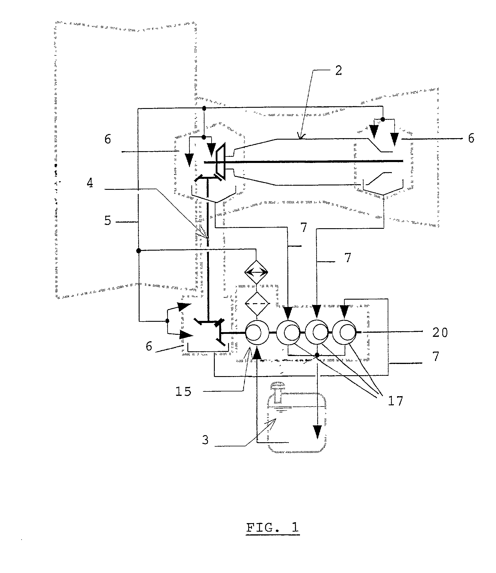
[0042] According to the prior art, as shown by the schematic view in FIG. 1, an assembly of lubrication pumps 15, 17 is arranged on a single shaft 20. This shaft is driven by a kinematic chain 4, which is in turn driven by the high-pressure shaft 2 of the engine.

[0043] The oil is first taken from the reservoir 3 and delivered by one or more pumps 15 to the various elements 6 to be lubricated, via a downstream circuit 5, and secondly recovered in the pan sections of the engine and returned by one or more pumps 17 to the reservoir 3, via a recovery circuit 7.

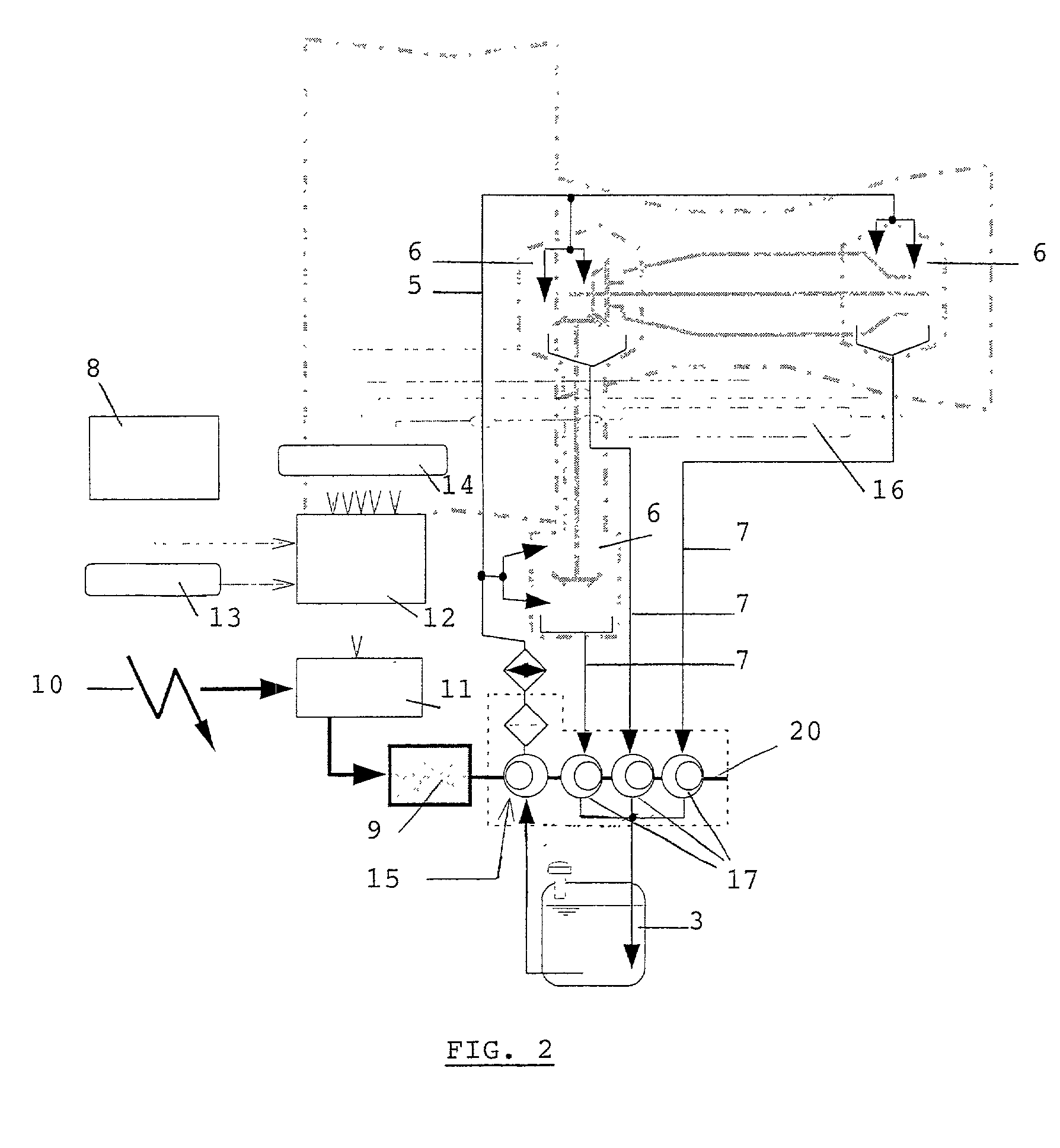
[0044] FIG. 2 is a diagram illustrating the general principles for the control of independently driven lubrication pumps, according to one preferred embodiment of the invention, in which all the pumps are grouped on a single shaft 20.

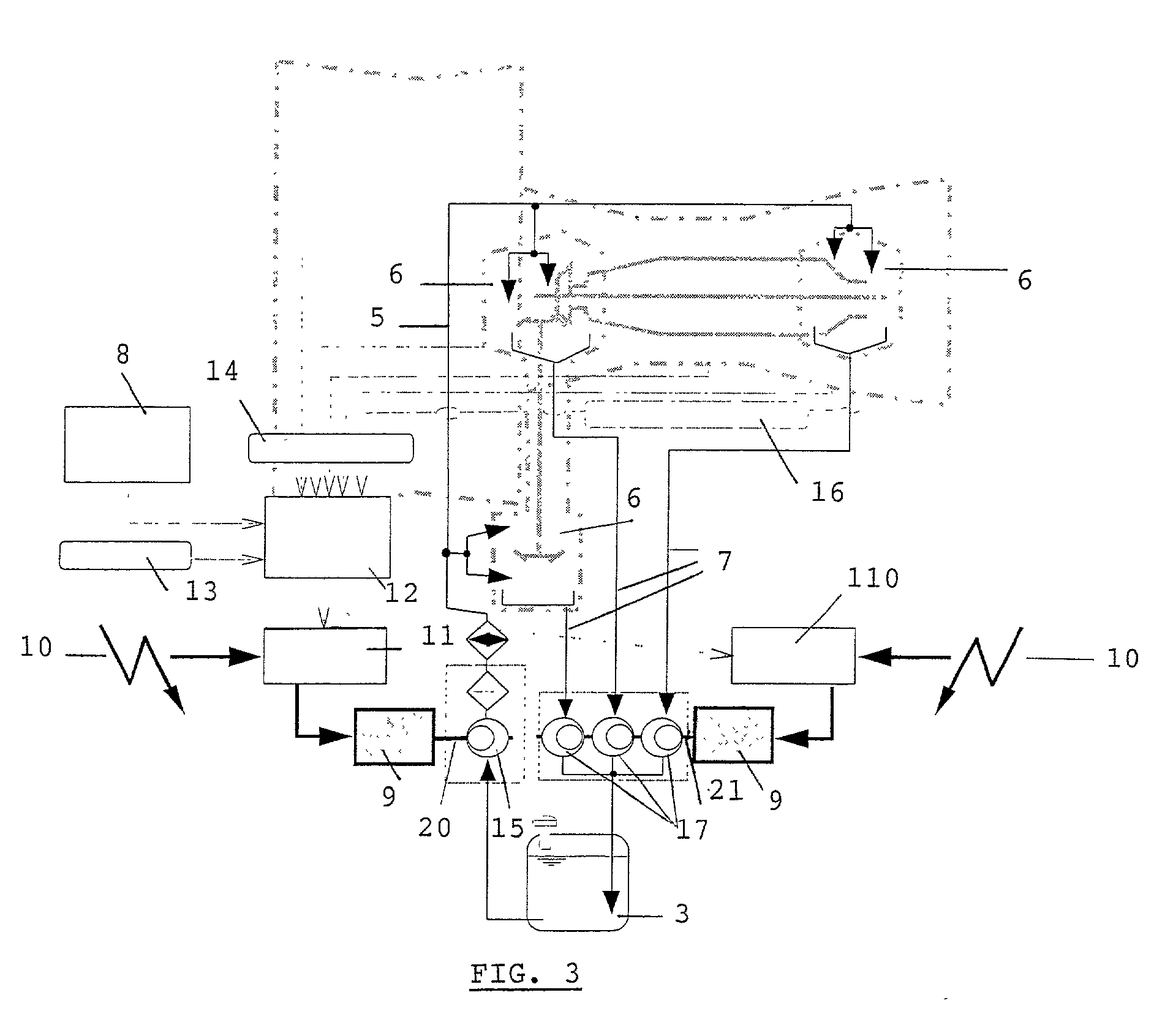
[0045] According to another specific embodiment of the invention shown in FIG. 3, the speed control unit 11 for the feed pump 15 is made separate from the common speed control unit 110 for all the rec...


PUM


Abstract

The present invention relates to a process for lubricating an aircraft engine, and preferably a turboreactor engine, comprising at least one shaft (2), in which the pressurization of oil taken from a reservoir (3), the distribution of the oil via a downstream circuit (5) to elements (6) of said engine, and the return of the oil via an upstream circuit (7) to the reservoir (3) are ensured by means of a pump (1, 15, 17), the rotational speed of said pump (1, 15, 17) being variable and adjustable, characterized in that this rotational speed of said pump (1, 15, 17) is preferably regulated by a predetermined law in order to adapt to the actual lubrication needs of said engine.

Description

SUBJECT OF THE INVENTION[0001] The present invention relates to a process and a device for lubricating an aircraft engine.STATE OF THE ART[0002] It is known that aircraft engines are lubricated by an assembly of pumps which, firstly, pressurize the oil taken from the reservoir and then delivered to the engine elements to be lubricated, and, secondly, recover the oil collected in the pan sections of the engine and conveyed to the reservoir. These pumps are all either driven by the same shaft as an "assembly of pumps" or distributed individually in the engine.[0003] For various reasons, these pumps are generally of volumetric or volume displacement type. The simple types, of fixed capacity, such as gear pumps, Gerotor.RTM. pumps and vane pumps, are preferred for reasons of simplicity, reliability and lightness.[0004] Like other engine accessories, these pumps are driven by the shaft of the high-pressure body of the engine by means of a more or less complex kinematic chain. The speed o...

Claims


Application Information

Patent Timeline
IPC IPC(8): F01D15/08F01D25/20
CPCF01D15/08F01D25/20F16N2210/02F16N2210/08Y02T50/671Y02T50/60
Inventor CORNET, ALBERT
Owner TECHSPACE AERO
Why Eureka
Try Eureka