Method and apparatus for the thermal clamping and releasing of tools

a technology of thermal clamping and tools, applied in the direction of chucks, chemistry apparatus and processes, manufacturing tools, etc., can solve the problems of only being suitable to a limited extent, only allowing for a limited extent of tool shrunk, and only allowing for a limited extent of device us

Inactive Publication Date: 2001-12-27
HARBIN MEASURING & CUTTING TOOL GROUP CO LTD
View PDF3 Cites 40 Cited by
  • Summary
  • Abstract
  • Description
  • Claims
  • Application Information

AI Technical Summary

Problems solved by technology

During shrinking in and in particular shrinking out of carbide tools by means of hot air devices, as a result of the different thermal expansion coefficients of the tool material and the shrink chuck material problems do not generally arise, but in the case of tools with HSS and steel shanks, particularly when shrinking out problems can occur, because in this case the thermal expansion behavior of the tool material and the chuck material is similar and with slow heating the tool shank can be enlarged to such an extent in the widening tool reception opening that the tool continues to be held by the widening reception opening and cannot be removed or can only be removed by exerting force.
Energy introduction by means of an induction coil surrounding the shrink chuck can take place so rapidly that a temperature rise of shrunk in tools only occurs to a limited extent by heat conduction.
The resulting handling of the device has proved to be problematical.
It has also been found that the device is only suitable to a limited extent for a rapid passage of higher numbers, because there is a slow overall system heating.
Operators have also considered it to be disadvantageous that in part still hot chucks have to be moved in order to achieve a higher throughput.
This also ensures that the heat introduced on heating is not spread through the receptacle to the entire shrinkage device, which could lead to a slow heating of the overall system and to operating problems.

Method used


Image

  • Method and apparatus for the thermal clamping and releasing of tools
  • Method and apparatus for the thermal clamping and releasing of tools
  • Method and apparatus for the thermal clamping and releasing of tools

Examples


Embodiment Construction

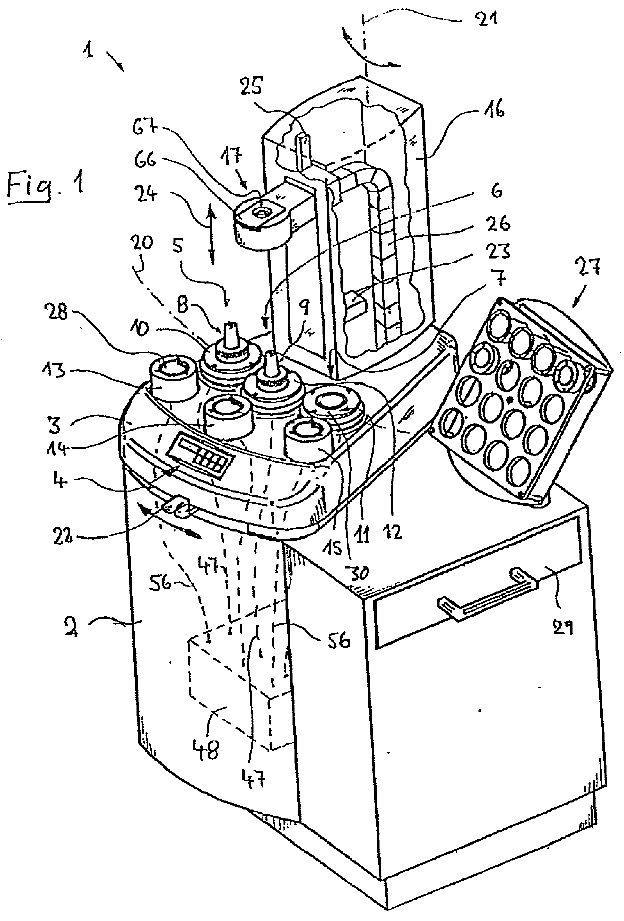
[0046] FIG. 1 is an inclined perspective, diagrammatic view of an apparatus 1, also referred to as shrinking apparatus or device for the thermal clamping and releasing or unclamping of tools with respect to shrink chucks, which makes it possible in continuous operation to clamp or release a large number of high speed machining tools in short sequence by means of shrinkage technology, in order to e.g. obtain a highly efficient work place with a high tool throughput. The embodiment shown comprises a closed lower cabinet 2, in which are housed subsequently described supply units for the shrinking device, such as a high frequency generator for supplying an induction coil, a cooling unit of a water cooling device and an electronic control for the shrinking device equipped with a microprocessor. On the roughly hip-high top of the lower cabinet is fixed a substantially tart piece-shaped closed base part 3 with a casing in the form of an aluminum casting. On its sloping front the base part ...


PUM

PropertyMeasurementUnit
diametersaaaaaaaaaa
diametersaaaaaaaaaa
opening angleaaaaaaaaaa

Abstract

A shrinking device (1) for the thermal clamping and release of tools in shrink chucks has a preferably inductively operating heating device (17) for heating tool reception sections of shrink chucks and a cooling device for the active cooling of the heated shrink chucks. The device has several, particularly three work stations (5, 6, 7) and in each work station it is possible both to heat a shrink chuck and also actively cool the shrink chuck received. By pivoting a column (16) carrying the heating device it is possible to interchange between the workstations. The shrinking apparatus makes it possible on a continuous basis to shrink large numbers of tools.

Description

[0001] 1. Field of the Invention[0002] The invention relates to a method and an apparatus for the thermal clamping and releasing of tools in shrink chucks.[0003] 2. Description of the Prior Art[0004] Shrinkage is a known method for the manufacture of high-speed tools for material-removing workpiece machining. Use is made of so-called shrink chucks, which have a tool reception section with an at least zonally thermally widenable tool reception opening for receiving a tool shank, as well as a clamping section provided in a machine spindle for receiving the clamp chuck and which can e.g. be constructed in the manner of a steep taper or a hollow shank taper. Typical diameters of the tools to be shrunk in, e.g. in the form of drilling, milling or grinding tools can be approximately 3 to 6 mm to approximately 30 to 40 mm. For the manufacture of a tool at least one portion of the tool reception section is heated to such an extent that as a result of thermal expansion the tool reception ope...

Claims


Application Information

Patent Timeline
Patent Type & Authority Applications(United States)
IPC IPC(8): B23B31/02B23P11/02H05B6/14H05B6/38H05B6/42
CPCB23B31/1179B23P11/027Y10T29/49865H05B6/38H05B6/42H05B6/14
Inventor KELCH, MATTHIAS
Owner HARBIN MEASURING & CUTTING TOOL GROUP CO LTD
Why Eureka
Try Eureka