
Drive rod for a high-voltage circuit-breaker

Inactive Publication Date: 2002-01-10
ALSTOM TECH LTD
View PDF0 Cites 2 Cited by
  • Summary
  • Abstract
  • Description
  • Claims
  • Application Information

AI Technical Summary

Benefits of technology

[0004] An object of the invention is to provide another form of protection for such an insulating rod that is simple to implement and that does not suffer from the above-indicated drawbacks.

Problems solved by technology

In spite of this deflector, the insulating segment of the rod is subjected to very considerable thermal attack (burns) that can give rise to an unacceptable reduction it is dielectric strength.
Unfortunately, with those protection techniques, it is difficult to avoid problems of air being included in the interface between the insulating segment and the protection.

Method used


Image

  • Drive rod for a high-voltage circuit-breaker
  • Drive rod for a high-voltage circuit-breaker

Examples


Embodiment Construction

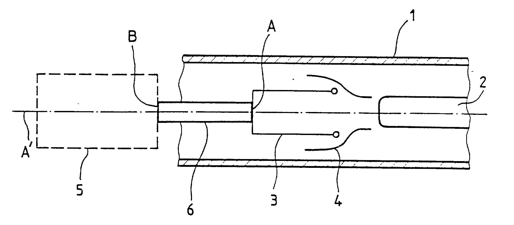
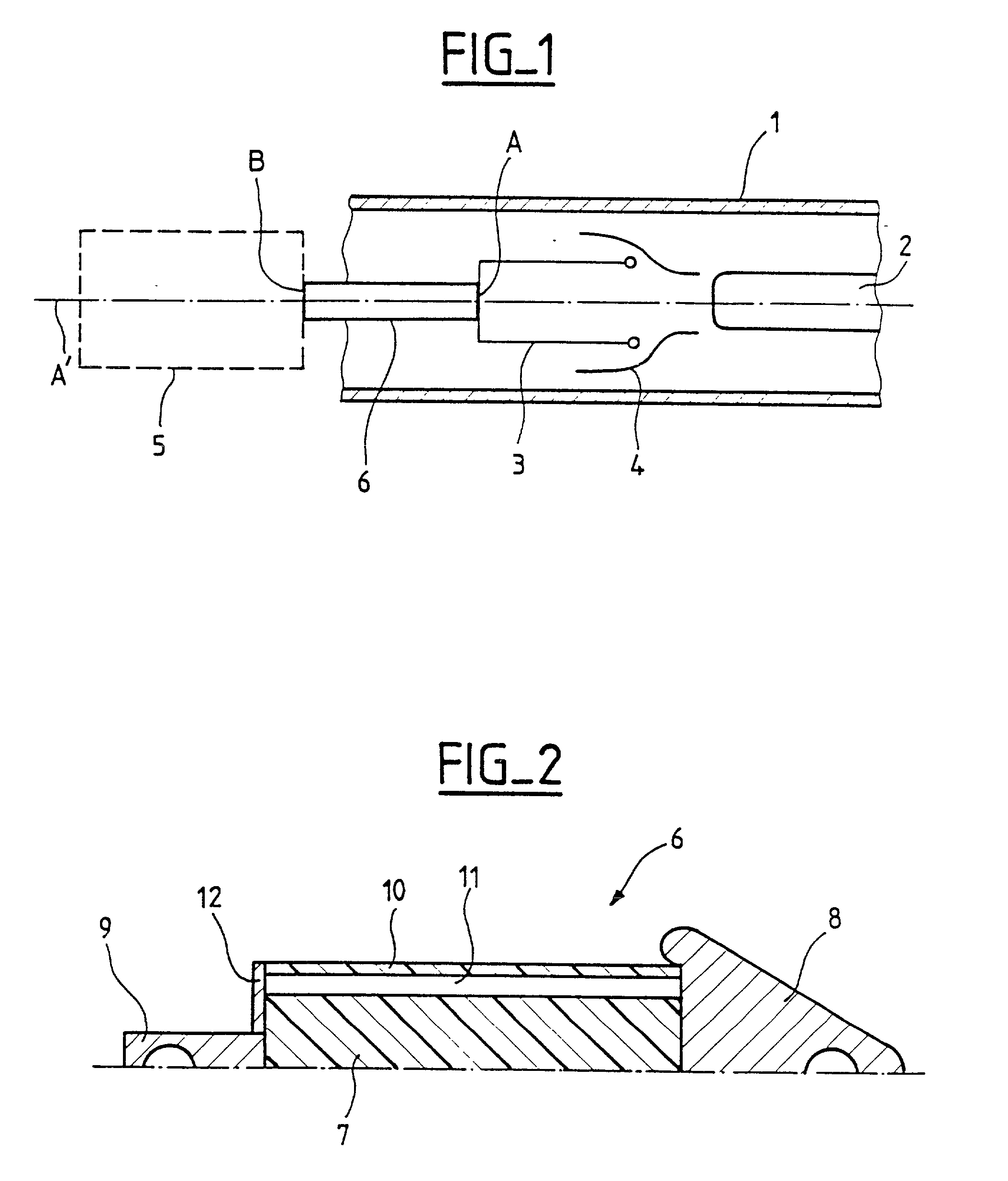
[0011] As shown in FIG. 1, a power station circuit-breaker conventionally comprises the following in a casing 1 made of an electrically-insulating material and filled with an insulating dielectric gas such as SF.sub.6 at a pressure of a few bars: a fixed contact 2, and a moving contact 3 with a gas-blast nozzle 4 for extinguishing electric arcs. The moving contact 3 is moved in the axial direction A' by a control mechanism 5 via a drive rod 6 having one of its ends A connected to the back of the moving contact 3, and its other end B connected to the control mechanism 5.

[0012] As shown in FIG. 2, the drive rod 6 comprises a segment 7 that is made of an electrically-insulating material, that may be either solid or hollow, and that is generally cylindrical. One end of the segment is fixed to a first metal endpiece 8 forming a deflector and constituting the end A of the rod, and the other end of the segment is fixed to a second metal endpiece 9 constituting the end B of the rod. A therm...


PUM


Abstract

The drive rod for high-voltage switchgear that is insulated with a dielectric gas comprises a segment made of an electrically-insulating material and two metal endpieces fixed to respective ends of the segment, as well as a thermal shield that is made of an electrically-insulating material, that is disposed between the endpieces, and that surrounds the insulating segment while being spaced apart therefrom to define an annular gap serving to be filled with the dielectric gas. In this way, the insulating segment of the rod is protected against thermal attack from electric arcs.

Description

[0001] The present invention relates to high-voltage circuit-breakers or to other switchgear that is insulated with a dielectric gas, and it relates more particularly to the drive rod for driving the moving contact of a circuit-breaker of a power station, which drive rod is interposed between the moving contact and the control mechanism of the circuit-breaker.[0002] The drive rod for driving a moving contact of a high-voltage circuit-breaker in a power station generally comprises a cylindrical segment that can be either solid or hollow, and that is made of an electrically-insulating material, e.g. glass fiber reinforced with resin, and two metal endpieces fixed to respective ends of the insulating segment, one of the endpieces serving to be connected to the moving contact of the circuit-breaker, the other endpiece serving to be connected to the control mechanism.[0003] In known manner, the metal endpiece of the rod that serves to be connected to the moving contact of the circuit-bre...

Claims


Application Information

Patent Timeline
IPC IPC(8): H01H33/42H02B13/02
CPCH01H33/42H01H2033/426
Inventor MAHL, MAURICEWILLIEME, JEAN-MARC
Owner ALSTOM TECH LTD
Learn More