Method for determining poses of sensors

a technology for sensors and poses, applied in direction finders, direction finders using radio waves, instruments, etc., can solve the problems of insufficient constrained problems, decomposition and other problems, and achieve the effect of simple and fast implementation, stable number of results

Active Publication Date: 2006-02-28
MITSUBISHI ELECTRIC RES LAB INC
View PDF1 Cites 16 Cited by
  • Summary
  • Abstract
  • Description
  • Claims
  • Application Information

AI Technical Summary

Benefits of technology

[0014]For camera images, the spectral decomposition yields a solution that is consistent to a fraction of a millimeter, improving over the state of the art calibration methods by four orders of magnitude. The method is also faster by at least two orders of magnitude.
[0015]In contrast with the prior art iterative process, the method according to the invention provides closed-form solutions in linear time that are numerically stable. The method is simple and fast to implement.

Problems solved by technology

The spectral decomposition also identifies insufficiently constrained problems, which can then be decomposed into well-constrained rigid sub-problems.

Method used


Image

  • Method for determining poses of sensors
  • Method for determining poses of sensors
  • Method for determining poses of sensors

Examples


Embodiment Construction

System Structure

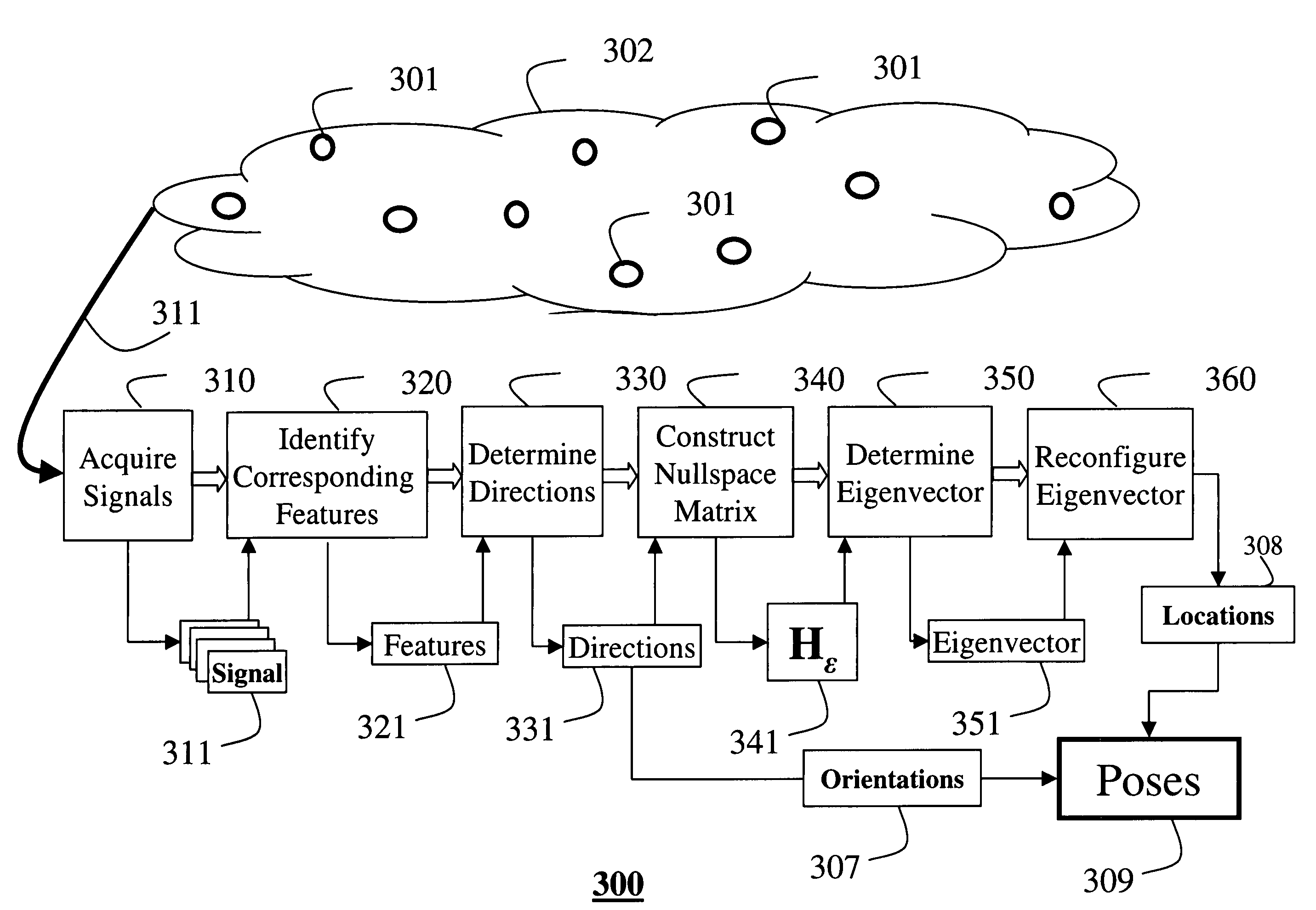
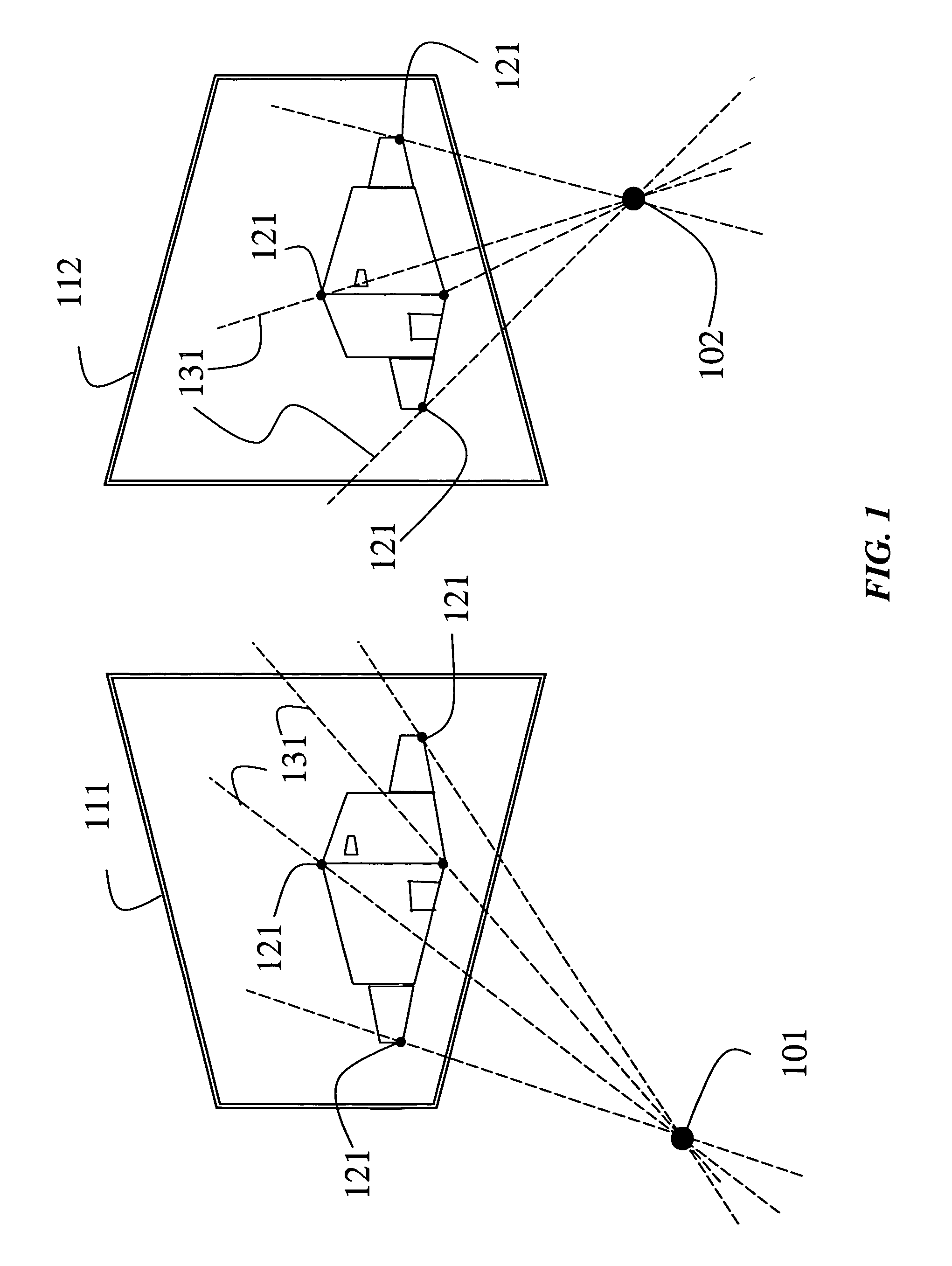
[0023]FIG. 1 shows sensors or ‘nodes’101–102, e.g., cameras. A method according to my invention determines the poses of the sensors by analyzing signals 111–112, e.g., images, acquired by sensors. As a characteristic, the signals are acquired of a large environment, for example, an urban area, or a portion of the universe. Each signal has only a small number of features 121 in common with another signal. Consequently, the signals are said to be sparse.

[0024]The method according to my invention treats this problem as a graph embedding problem. Prior art solutions typically constrain a pose of a node by linear mixtures of directions to neighboring nodes, with a known mixture weights, see Roweis et al., “Nonlinear dimensionality reduction by locally linear embedding,” Science 290, pp. 2323–2326, 2000.

[0025]Similarly, my method constrains node poses to be linear mixtures of directions 131 between nodes and features 121, however, with an unknown mixture weights. The direc...


PUM


Abstract

A method determines poses of a sensors distributed in an environment. A signal of the environment is acquired by each sensor. Features in each signal that correspond to the features in at least one other signal are identified. Directions between the sensors and the corresponding features are determined. Nullspaces of the directions are used to construct a matrix. A nullspace eigenvector is determined of the matrix, and then the nullspace eigenvector is reconfigured to a matrix specifying the locations of the sensors.

Description

FIELD OF THE INVENTION[0001]This invention relates generally to sensors, and more particularly to determining poses of the sensors.BACKGROUND OF THE INVENTION[0002]In many computer applications it is necessary to determine poses of sensors relative to sensed features in the environment in which the sensors are located. The pose of a sensor gives both the location and the orientation of the sensor. In three-dimensions, the location is usually specified by a three-dimensional Cartesian coordinate system (x,y,z), and the orientation is specified by a three-dimensional polar coordinate system (u,v,w).[0003]For example, many computer vision and graphics applications require that the poses of cameras are known. These applications include three-dimensional reconstructions, modeling by structure-from-motion, photo-realistic rendering, image based environment augmentation, simulation, and image registration, to name but a few.[0004]In a simple application, signals in the form of stereo image...

Claims


Application Information

Patent Timeline
Patent Type & Authority Patents(United States)
IPC IPC(8): G01C17/00G01S3/02G01C11/00G01C11/06
CPCG01C11/06
Inventor BRAND, MATTHEW E.
Owner MITSUBISHI ELECTRIC RES LAB INC
Why Eureka
Try Eureka