Automatic clamping jig for mobile phone production and clamping method

A mobile phone and clamping technology, which is applied in the field of automatic clamping fixtures and clamping for mobile phone production, can solve problems such as manual operation, increased labor costs and time costs, and inability to clamp samples to be tested, so as to reduce the time used , reduce labor costs and improve efficiency

Active Publication Date: 2020-12-04
南京雷石电子科技有限公司
View PDF11 Cites 3 Cited by
  • Summary
  • Abstract
  • Description
  • Claims
  • Application Information

AI Technical Summary

Problems solved by technology

[0003] The purpose of the present invention is to provide an automatic clamping fixture and clamping method for mobile phone production, to solve the problem that the clamping of the mobile phone during the test proposed in the background technology is manually operated, and the test sample cannot be clamped in a short time. It will increase the cost of manpower and time, so that the efficiency of mobile phone testing cannot be further improved

Method used


Image

  • Automatic clamping jig for mobile phone production and clamping method
  • Automatic clamping jig for mobile phone production and clamping method
  • Automatic clamping jig for mobile phone production and clamping method

Examples


Embodiment 1

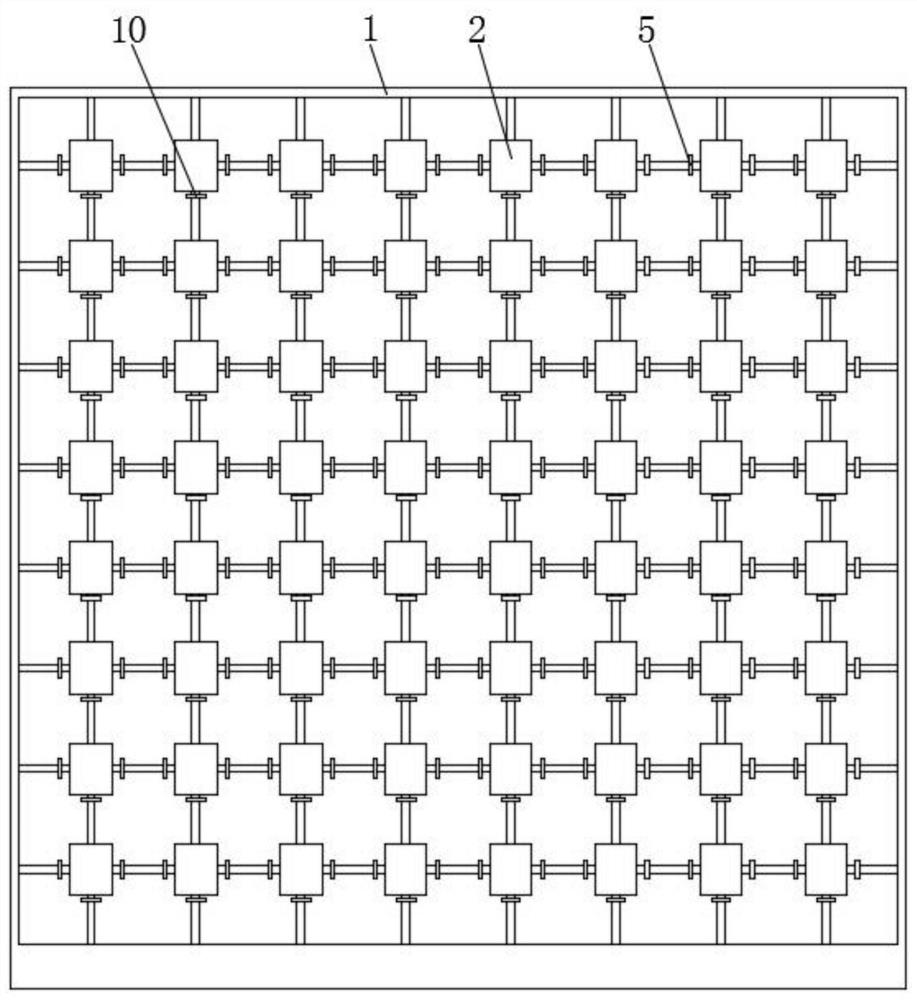
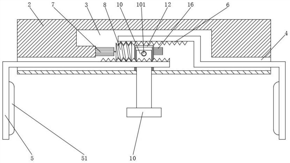
[0027] see Figure 1-5 , the present embodiment provides an automatic clamping jig for mobile phone production, including a vertically fixed mounting frame 1, a plurality of mounting plates 2 distributed in an array are fixed on the front of the mounting frame 1, and the interior of the mounting plate 2 A movable chamber 3 is provided, and the two sides of the placement plate 2 are far away from each other and near the middle, there is a movable port 4 connected with the movable chamber 3, and a splint 5 is installed inside the movable port 4, and the splint 5 extends into the side of one end of the movable port 4 A rack 6 is fixed, and a telescopic motor 7 is fixed inside the movable chamber 3. The power output shaft of the telescopic motor 7 is fixed with a worm 8 meshing with the rack 6. Through telescopic mouth 9, the inside of telescopic mouth 9 is equipped with support plate 10, and the inner wall of movable cavity 3 bottom side is extended to be provided with slideway 1...

Embodiment 2

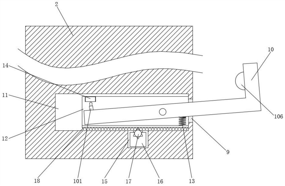
[0041] see Figure 3-4 A further improvement has been made on the basis of Embodiment 1: a movable cylinder 101 is integrally provided on the top side of the end of the support plate 10 directly below the pressure sensor 14, and a movable rod 102 is installed inside the movable cylinder 101, and the movable cylinder 101 is far away from the opening end. A back-moving spring 103 is installed between the inner wall and the movable rod 102, and the inner wall of the movable cylinder 101 near the open end is integrally provided with a limit ring 104, and the outer wall at the bottom end of the movable rod 102 is provided with a limit ring 105 matched with the limit ring 104, and the movable rod 102 The top of the movable rod 102 is one-half of a spherical structure, and the pressure sensor 14 can measure a stable pressure in a relatively long period of time by sliding inside the movable cylinder 101 after the top of the movable rod 102 touches the pressure sensor 14 value, which c...


PUM


Abstract

The invention discloses an automatic clamping jig for mobile phone production and a clamping method. The jig comprises a placement frame fixed in a vertical direction, a placement plate is fixed to the front surface of the placement frame, a movable cavity is formed in the placement plate, movable openings are formed in the two sides, away from each other, of the placement plate, clamping plates are installed in the movable openings, and racks are fixed to the side surfaces of the clamping plates. A telescopic motor is fixed in the movable cavity, a sliding way is formed in the movable cavity,a sliding groove is formed in the sliding way, the supporting plate is hinged to the interior of the sliding groove, a pressure sensor is arranged right above one end of the sliding groove, a fixed cavity is formed in the bottom side of the sliding way, a reset motor is installed in the fixed cavity, and the output end of the pressure sensor is connected with a single-chip microcomputer. A distance sensor is installed at the top end of the placement plate. Through cooperative use of the devices, clamping and fixing of a mobile phone during testing can be automatically completed, a labor expenditure is reduced, time for clamping and fixing a mobile phone sample is shortened, and mobile phone testing efficiency is improved.

Description

technical field [0001] The invention relates to the technical field of mobile phone production clamping equipment, in particular to an automatic clamping fixture and clamping method for mobile phone production. Background technique [0002] The finished products produced by mobile phones need to be sampled and tested. The mobile phones used as samples need to be fixed one by one. The fixing of mobile phones is mostly done manually. When the mobile phone needs to be removed, the workload of the staff will be increased again, resulting in increased labor costs and time costs, which cannot further improve the efficiency of mobile phone testing. Contents of the invention [0003] The purpose of the present invention is to provide an automatic clamping fixture and clamping method for mobile phone production, to solve the problem that the clamping of the mobile phone during the test proposed in the background technology is manually operated, and the test sample cannot be clamped...

Claims


Application Information

Patent Timeline
Patent Type & Authority Applications(China)
IPC IPC(8): H04M1/04H04M1/24G01B11/02G01L5/00
CPCG01B11/02G01L5/00H04M1/04H04M1/24
Inventor 赵安东
Owner 南京雷石电子科技有限公司
Why Eureka
Try Eureka