Network management system

a network management and network technology, applied in the field of network management system, can solve problems such as the inability to avoid the deterioration of communication quality over the entire network

Inactive Publication Date: 2002-01-24
FUJITSU LTD
View PDF4 Cites 14 Cited by
  • Summary
  • Abstract
  • Description
  • Claims
  • Application Information

AI Technical Summary

Problems solved by technology

However, since the quality policy is not set in the router RT3, it is not possible to provide the service according to the determined quality policy for the data packets passing through the router RT3 until the L3 fault man

Method used


Image

  • Network management system
  • Network management system
  • Network management system

Examples


Embodiment Construction

[0082] FIG. 4 shows an embodiment of the connecting information of the nodes of the lower layer L2 (L2 nodes) and the upper layer L3 (L3 nodes) stored in the inter-layer node connecting information storage portion 300 in the network management system according to the present invention schematically shown in FIG. 1. For example, in FIG. 4, the SW1 / port1 of the L2 node is associated with or made corresponding to the RT1 / port1 of the L3 node in the form of a table.

[0083] An operational embodiment when using such an inter-layer node connecting information storage portion 300 will be described herebelow referring to FIG. 5.

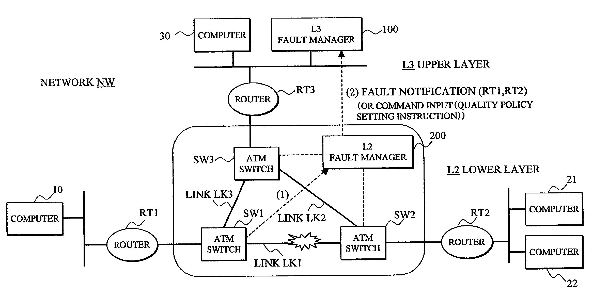
[0084] Firstly, the arrangement of the hierarchical network NW in FIG. 5 is basically the same as that of the network NW shown in FIG. 11.

[0085] Namely, the ATM switches SW1-SW3 composing the lower layer L2 are respectively connected to the routers RT1-RT3 composing the upper layer L3.

[0086] Also, the computer 10 is connected to the router RT1, the computers 21 and 22 ...


PUM


Abstract

In a network management system performing a fault management process in a hierarchical network, an upper layer fault manager performs a fault management of an upper layer of a hierarchical network, a lower layer fault manager performs a fault management of a lower layer of the network, an inter-layer node connecting information storage portion manages connecting information between packet switching nodes composing the upper layer and link offering nodes composing the lower layer, and an inter-layer fault notifying portion notifies the upper layer fault manager, upon receiving a notification of a link fault which has occurred on a link between the link offering nodes from the lower layer fault manager, that the packet switching nodes affected by the fault are faulted, based on the connecting information.

Description

[0001] 1. Field of the Invention[0002] The present invention relates to a network management system, and in particular to a network management system performing a fault management process in a hierarchical network.[0003] 2. Description of the Related Art[0004] A fault restoration process in a prior art hierarchical (layered) network management system is performed closed in each layer, in many cases. Specifically, in an Internet Protocol (IP) network which has been used increasingly in recent years, a method of performing an independent fault management in each layer is generally known due to a historical background that management entities or managers for an IP layer and a lower layer thereof are different.[0005] FIG. 11 shows a schematic diagram of the prior art network management system. ATM switches SW1-SW3 composing a lower layer L2 of a hierarchical network NW, which is an IP network, are respectively connected to routers RT1-RT3 composing an upper layer L3.[0006] The ATM switc...

Claims


Application Information

Patent Timeline
IPC IPC(8): H04L12/24
CPCH04L41/044H04L41/06
Inventor UENO, HITOSHIISEDA, KOHEIFUKUDA, KENICHI
Owner FUJITSU LTD
Why Eureka
Try Eureka