Optical system for head mounted display

a technology of optical system and display, which is applied in the field of head mounted displays, can solve problems such as increased production costs

Inactive Publication Date: 2002-02-07
DAEYANG ENG
View PDF0 Cites 65 Cited by
  • Summary
  • Abstract
  • Description
  • Claims
  • Application Information

AI Technical Summary

Problems solved by technology

Although the conventional optical systems constructed as such have advantages in that their constitutions are simple and thus their production costs are low, there are still disadvantages in that the eye lens 3 should be thick since a focal length thereof must be shortened to realize a l...

Method used


Image

  • Optical system for head mounted display
  • Optical system for head mounted display
  • Optical system for head mounted display

Examples


Embodiment Construction

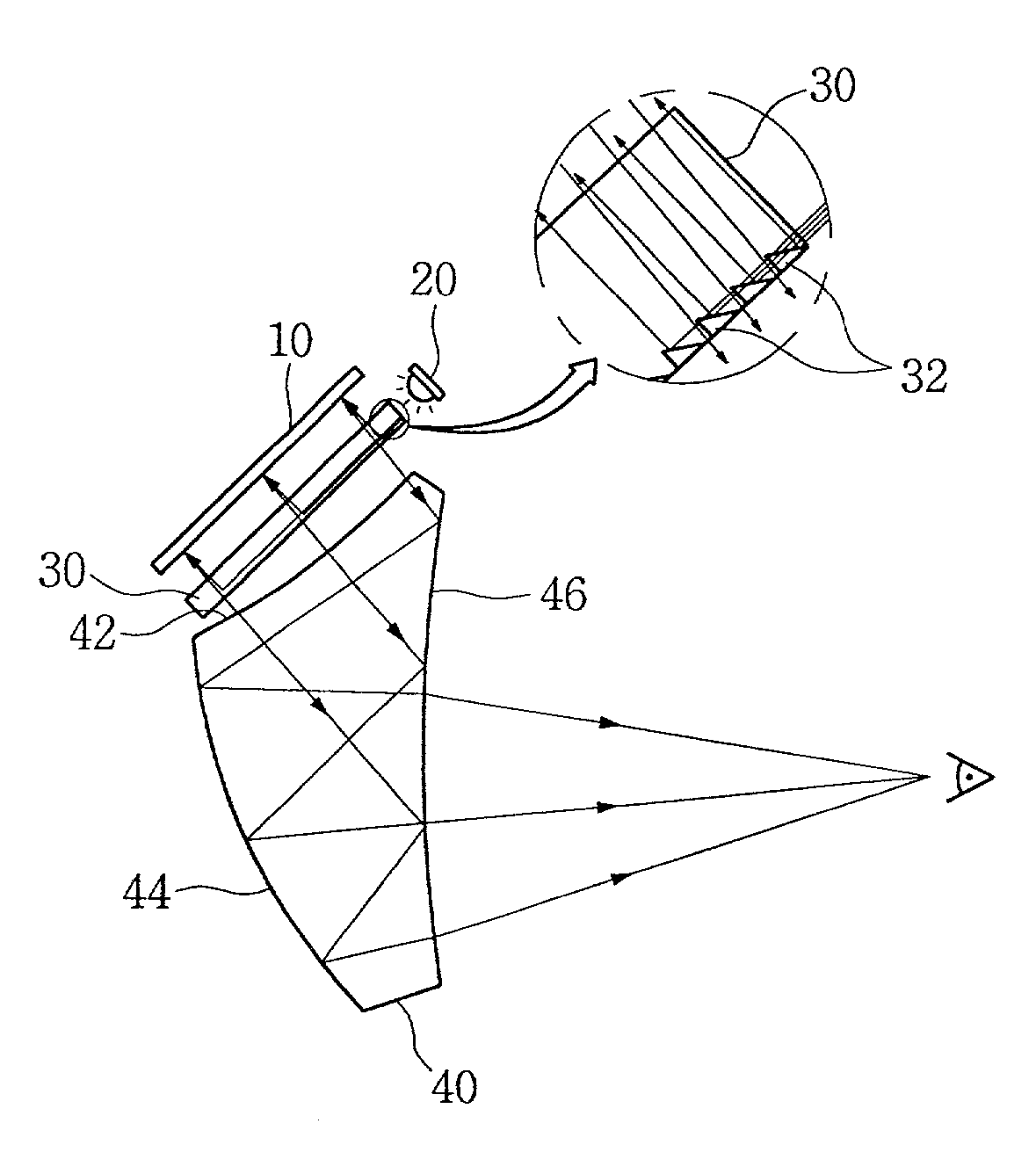
[0014] Hereinafter, a preferred embodiment of an optical system for a head mounted display according to the present invention will be explained in detail with reference to the accompanying drawings.

[0015] FIG. 4 is a view showing schematically the constitution and arrangement of the optical system for the head mounted display according to the present invention. First, as shown in FIG. 4, the optical system for the head mounted display according to the present invention includes a liquid crystal display screen 10, as a component thereof, for displaying an image. The liquid crystal display screen 10 is a high pixel density frontlight liquid crystal display screen for displaying the image by using irradiation from a light source disposed in front of the screen, and is disposed to face downward at an angle of about 45.degree.. Since the frontlight liquid crystal display screen has been well known, the detailed description thereof will be omitted.

[0016] Further, a red / green / blue (RGB) li...


PUM


Abstract

The present invention relates to a head mounted display that is constructed such that stereoscopic images can be seen on a liquid crystal display screen disposed adjacent to two human eyes. The present invention provides an optical system for a head mounted display, comprising a light source; a light guide panel which has a side portion, a top portion and a bottom portion, which receives light rays emitted from the light source through the side portion, reflects the light rays substantially perpendicular to a direction of the light rays, and emits the light rays toward the top portion, and which emits most of the light rays incident on the top portion through the bottom portion; a frontlight liquid crystal display screen which is disposed to face the top portion of the light guide panel and on which images are displayed by reflecting the light rays emitted from the top portion of the light guide panel and causing the light rays to be incident on the top portion of the light guide panel; and a free-form-surface prism disposed in front of the bottom portion of the light guide panel for magnifying the images on the liquid crystal display screen by reflecting and focusing the light rays which are reflected from the frontlight liquid crystal display screen and emitted toward the bottom portion of the light guide panel. According to the an optical system for a head mounted display of the present invention, there is an advantage in that its production costs can be reduced, since the optical system for the head mounted display of the present invention employs the frontlight liquid crystal display screen which is inexpensive and has a high pixel density. Further, there is another advantage in that the use efficiency of the light source can be enhanced, since the optical system of the present invention includes the inexpensive light emitting diode and the light guide panel for reflecting the light rays emitted from the light emitting diode and focusing the light rays within a range of the predetermined angles.

Description

[0001] 1. Field of the Invention[0002] The present invention relates to a head mounted display which is constructed such that stereoscopic images can be seen on a liquid crystal display screen disposed adjacent to eyes, and more particularly, to an optical system for the head mounted display wherein its production costs can be reduced and best images can be provided to a wearer by enhancing use efficiency of a light source.[0003] 2. Description of the Prior Art[0004] A head mounted display includes an optical system comprising a liquid crystal display screen, an illuminating device, lenses, etc. This optical system allows images to be displayed on the liquid crystal display screen and can be variously constructed depending on an arrangement of the components for constituting the optical system. Examples of the optical system used generally in the prior art are schematically shown in FIGS. 1 and 2. Taking the figures into consideration, the optical system of FIG. 1 is constructed in ...

Claims


Application Information

Patent Timeline
IPC IPC(8): G02F1/13G02B5/30G02B27/01G02B27/02G02F1/1335G02F1/13357H04N5/64
CPCG02B5/30G02B27/0172G02B27/01
Inventor PARK, BU GO
Owner DAEYANG ENG
Why Eureka
Try Eureka