Diagnostic ultrasound imaging based on rate subtraction imaging (RSI)

a technology of ultrasound imaging and rate subtraction, applied in the field of diagnostic ultrasound imaging, can solve the problems of affecting the blood flow speed, raising the problem of invasiveness, and the collapse phenomenon of contrast agents cannot be fundamentally avoided

Inactive Publication Date: 2002-03-07
TOSHIBA MEDICAL SYST CORP
View PDF0 Cites 47 Cited by
  • Summary
  • Abstract
  • Description
  • Claims
  • Application Information

AI Technical Summary

Problems solved by technology

However, the microbubbles are delicate substances, so they are characteristic of collapse due to irradiated ultrasound waves.
Although a contrast agent of high persistency and high durability has been developed recently, the collapse phenomenon of the contrast agent cannot be avoided fundamentally, because its main constituent is microbubbles.
Meanwhile, the long-term persistence of the contrast agent in a human body may raise the problem of invasiveness.
However, ultrasound waves are normally transmitted and received as many times as a few thousands per second, there is organ parenchyma whose blood flow speed is rather slow, and there is blood kinetics in relatively thin blood vessels.
However, it is not always possible for the conventional imaging to provide images of the perfusion with stability, there frequently occur the following problems.
One problem is that a diagnostic performance lowers due to a tissue harmonic signal.
Actually, however, there occur situations that make blood flow diagnosis difficult.
As a result, there occurs a problem that echo intensities of an internal organ itself is raised before injecting a contrast agent.
If this occurs, it is difficult to confirm whether or not echoes around thin blood vessels on images (particularly, a region with minute blood flows) acquired after the injection of the contrast agent are resulted from the contrast agent.
This problem is also true of the inverted phase pulse adding technique.
A second problem concerns with optimization for generation of images and processing of display.
However, when depicting echo signals from microbubbles of a contrast agent, it is not necessarily true that the foregoing tissue depiction processing is suitable for the depiction of such echo signals and they are depicted in an optimum state.
However, in such cases, there occurs the problem that the depiction of tissue of an internal organ is largely deviated from its optimum state so that its depiction performance is remarkably deteriorated.

Method used


Image

  • Diagnostic ultrasound imaging based on rate subtraction imaging (RSI)
  • Diagnostic ultrasound imaging based on rate subtraction imaging (RSI)
  • Diagnostic ultrasound imaging based on rate subtraction imaging (RSI)

Examples


first embodiment

[0068] Referring to FIGS. 1 to 11, a first embodiment of the present invention will now be described.

[0069] A diagnostic ultrasound apparatus according to the present invention can be applied to diagnosis of all regions of interest whose blood flow states can be observed based on contrasted degrees deriving from an injected ultrasound contrast agent into an object. The present embodiment, however, deals with a diagnostic ultrasound apparatus that has the function of identifying abnormal regions by acquiring data indicative of kinetics of blood flow on the basis of contrasted degrees of a contrast agent inflowing into the liver parenchyma or cardiac muscle (i.e. perfusion).

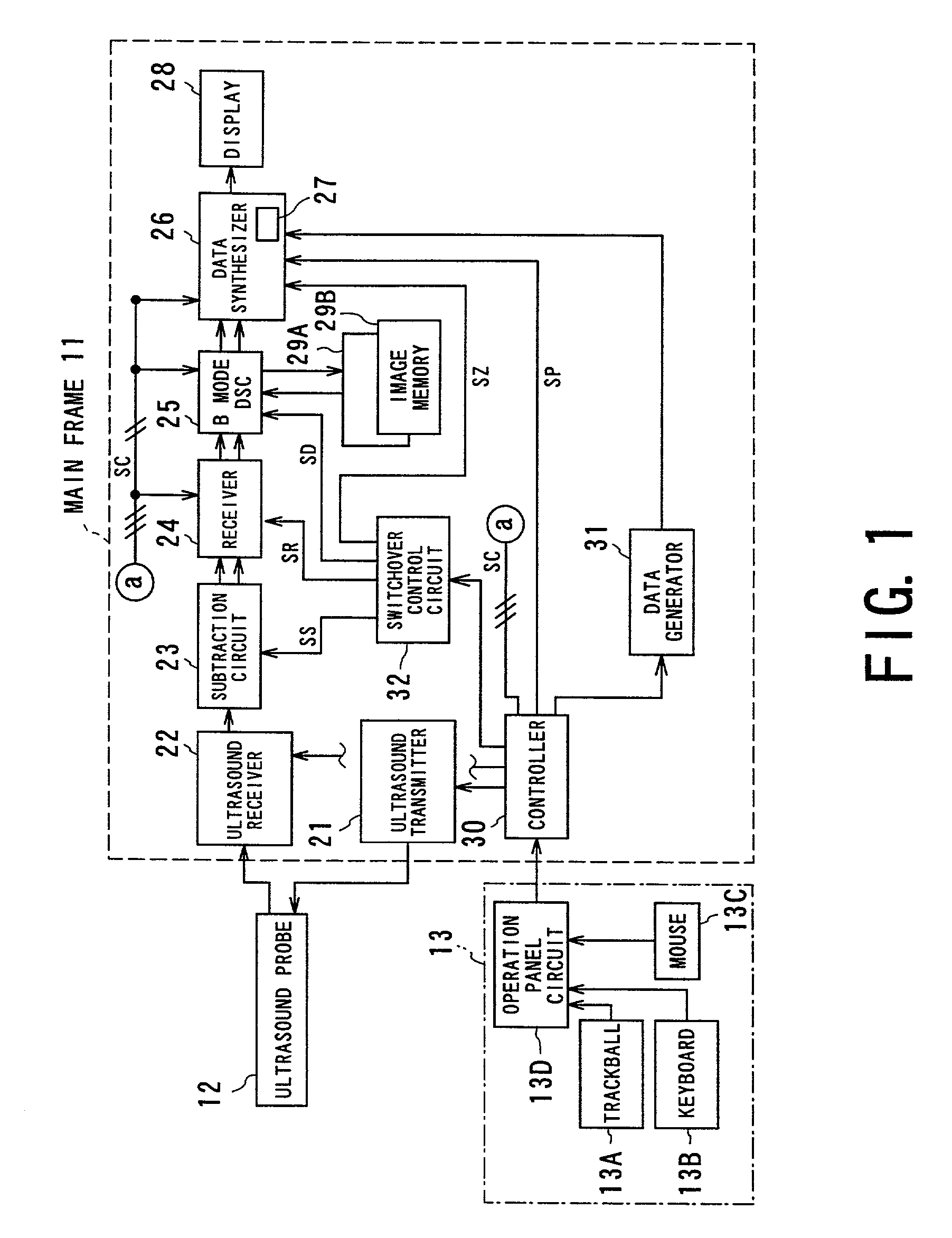
[0070] FIG. 1 schematically shows the entire configuration of a diagnostic ultrasound apparatus according to a first embodiment. The diagnostic ultrasound apparatus has a main unit 11, ultrasound probe 12 coupled with the main unit 11, and operation panel 13.

[0071] The operation panel 13 comprises a keyboard 13A, t...

second embodiment

[0156] Referring to FIG. 13, a diagnostic ultrasound apparatus according to the second embodiment will now be described.

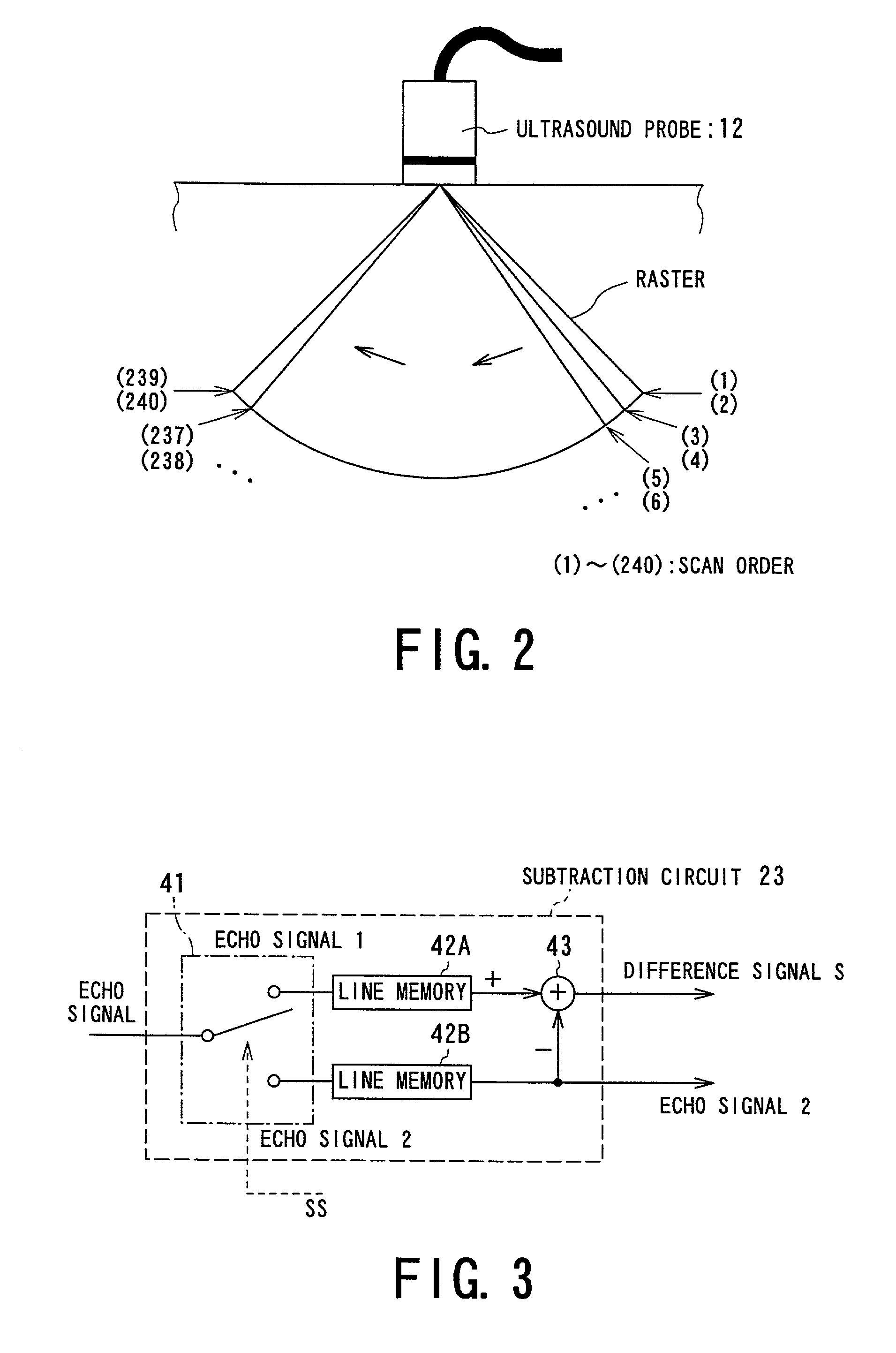
[0157] The present diagnostic ultrasound apparatus functions in the similar ways to that in the first embodiment, but differs from it in that the subtraction circuit 23 is configured as shown in FIG. 13. The remaining configurations are identical to those in the first embodiment.

[0158] As shown in FIG. 13, the subtraction circuit 23 is provided with the electric switch 41, the line memories 42A and 42B, the subtracter, and an adder 44. Compared to the configuration of FIG. 3, the adder 44 is newly installed. The adder 44 mutually adds signals read from the line memories 42A and 42B so as to produce an added signal A ="echo signal 1"+"echo signal 2." The produced signal A is outputted instead of the foregoing echo signal 2.

[0159] In other words, each of the difference signal S and added signal A is sent from the subtraction circuit 23 to its succeeding elements, in ...

third embodiment

[0162] Referring to FIG. 14A, a diagnostic ultrasound apparatus according to a third embodiment of the present invention will now be explained.

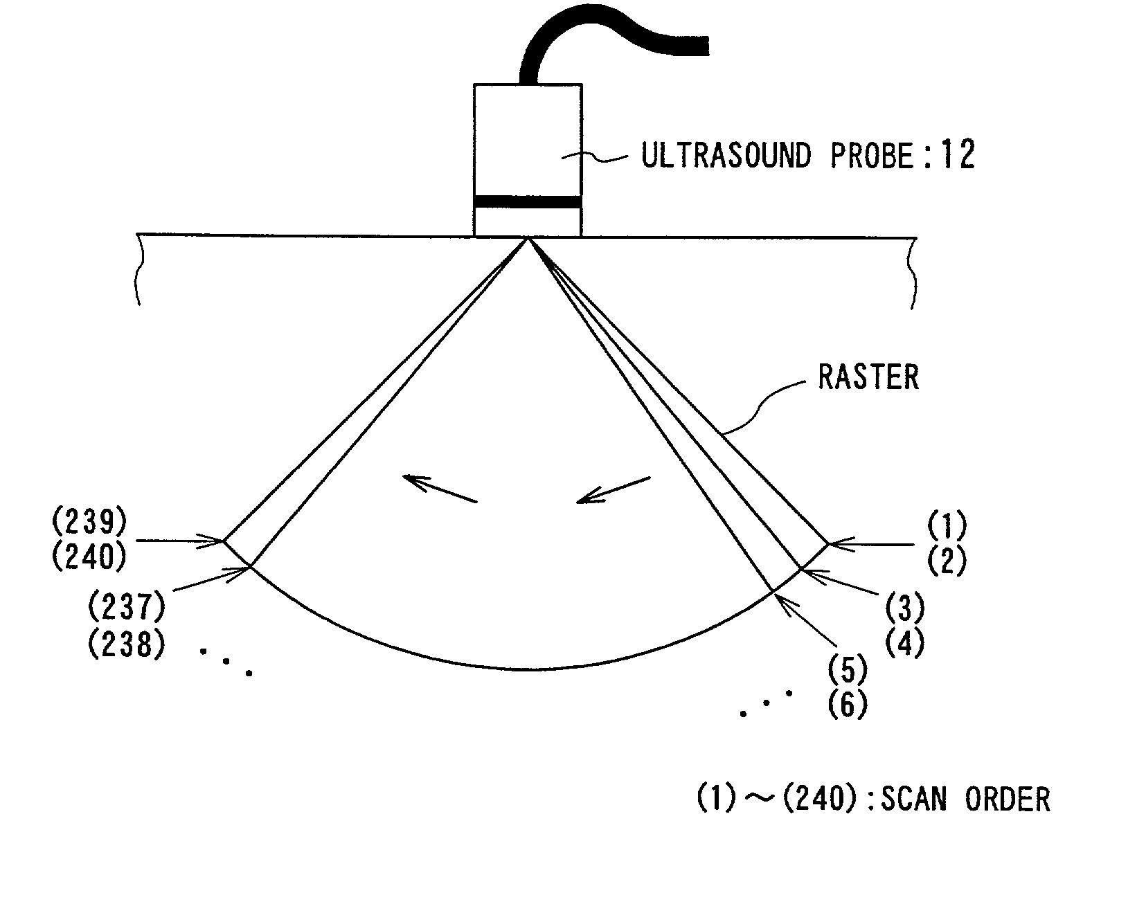
[0163] The diagnostic ultrasound apparatus is characterized by the number of scan times (the number of transmission and reception times) per one raster. That is, though the number of scan times is set to two times in the foregoing embodiments, it can be set to three or more times.

[0164] FIG. 14A shows one example, in which the number of scan times is assigned to three. When referring to this example, of all rasters of 100 pieces, the scan orders (1), (2) and (3) are assigned to the first raster, the scan orders (4), (5) and (6) are assigned to the adjacent raster, and so on. To the final raster, the scan orders (298), (299) and (300) are assigned. For each raster, a difference signal S is calculated from two signals depending on the first and third scans. The foregoing echo signal, which is paired with this difference signal S, is assigned to...


PUM


Abstract

In a diagnostic ultrasound apparatus, an ultrasound pulse signal is transmitted two times in each of the rasters on a region to be scanned. Subtraction between echo signals received at each time of transmission is made to obtain a difference signal. Either one of the echo signals and the difference signal are produced into individual tomographic images, independently of each other. The produced individual tomographic images are displayed with a superposed manner one on the other or parallel-arranged manner. This allows contrast echo imaging to be conducted on a rate subtraction imaging technique. Minute blood flows are depicted distinguishably from tissue surrounding those flows in a steady manner.

Description

[0001] 1. Field of the Invention[0002] The present invention relates to diagnostic ultrasound imaging by which imaging is performed based on a contrast echo technique for an object into which an ultrasound contrast agent of which main constituent is microbubbles is administered. In particular, the present invention relates to diagnostic ultrasound imaging capable of separating transient signals caused due to the microbubbles of the ultrasound contrast agent on the basis of a rate subtraction imaging (RSI) technique.[0003] 2. Description of the Related Art[0004] Ultrasound signals have been clinically used in various fields, and one field is an application to diagnostic ultrasound apparatus. A diagnostic ultrasound apparatus acquirers an image signal through transmission and reception of an ultrasound signal toward and from an object and is used in a variety of modes utilizing non-invasiveness of the signal.[0005] One typical type of diagnostic ultrasound apparatus produces tomograph...

Claims


Application Information

Patent Timeline
Patent Type & Authority Applications(United States)
IPC IPC(8): A61B8/00A61B8/06G01S7/52G01S15/89
CPCA61B8/463A61B8/481G01S7/52038G01S7/52074G01S7/52085
Inventor KAMIYAMA, NAOHISA
Owner TOSHIBA MEDICAL SYST CORP
Why Eureka
Try Eureka