

Methods and a user equipment for identification in a communications network
- Summary
- Abstract
- Description
- Claims
- Application Information
AI Technical Summary
Benefits of technology
Problems solved by technology
Method used
Image

Examples
Embodiment Construction
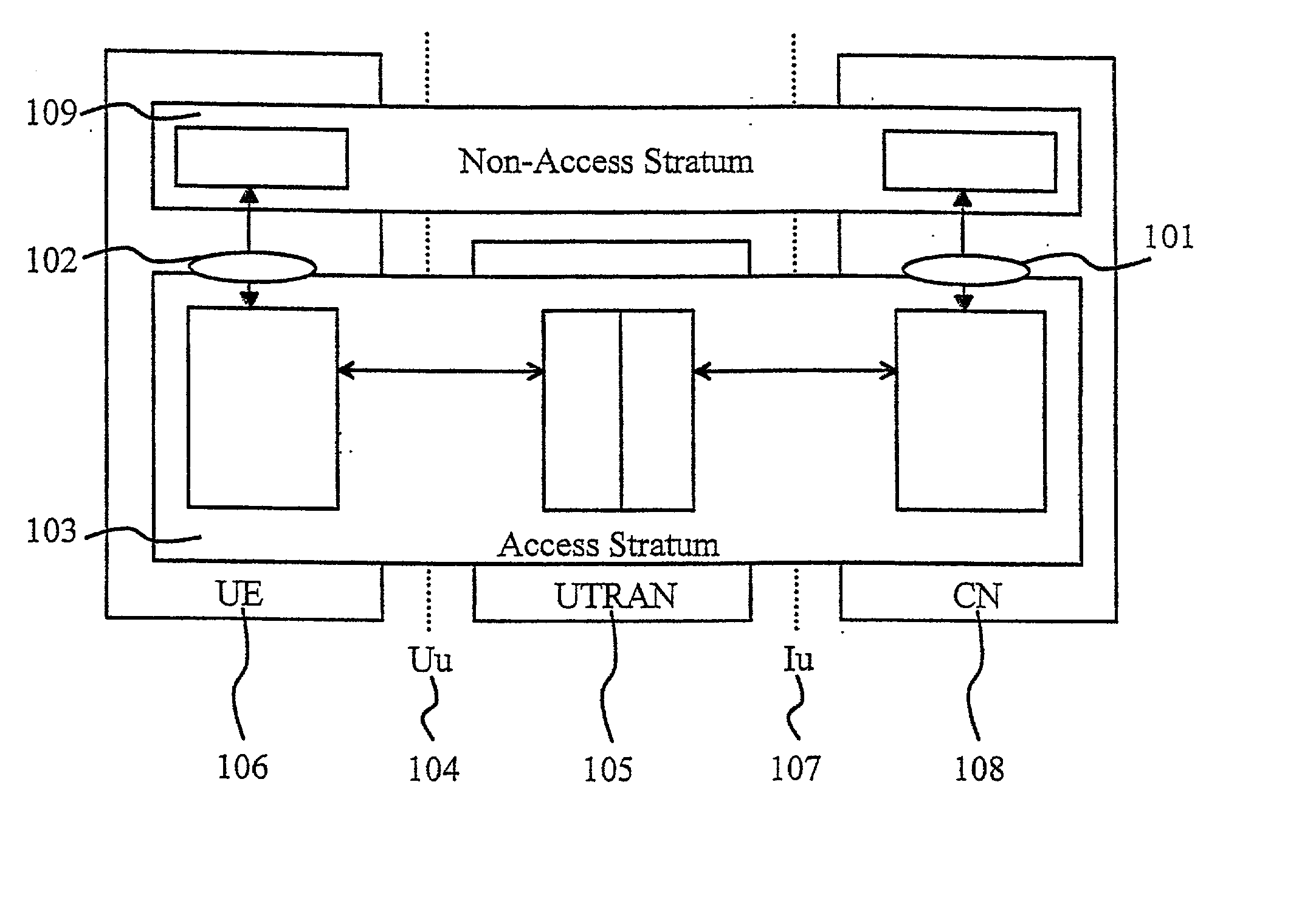
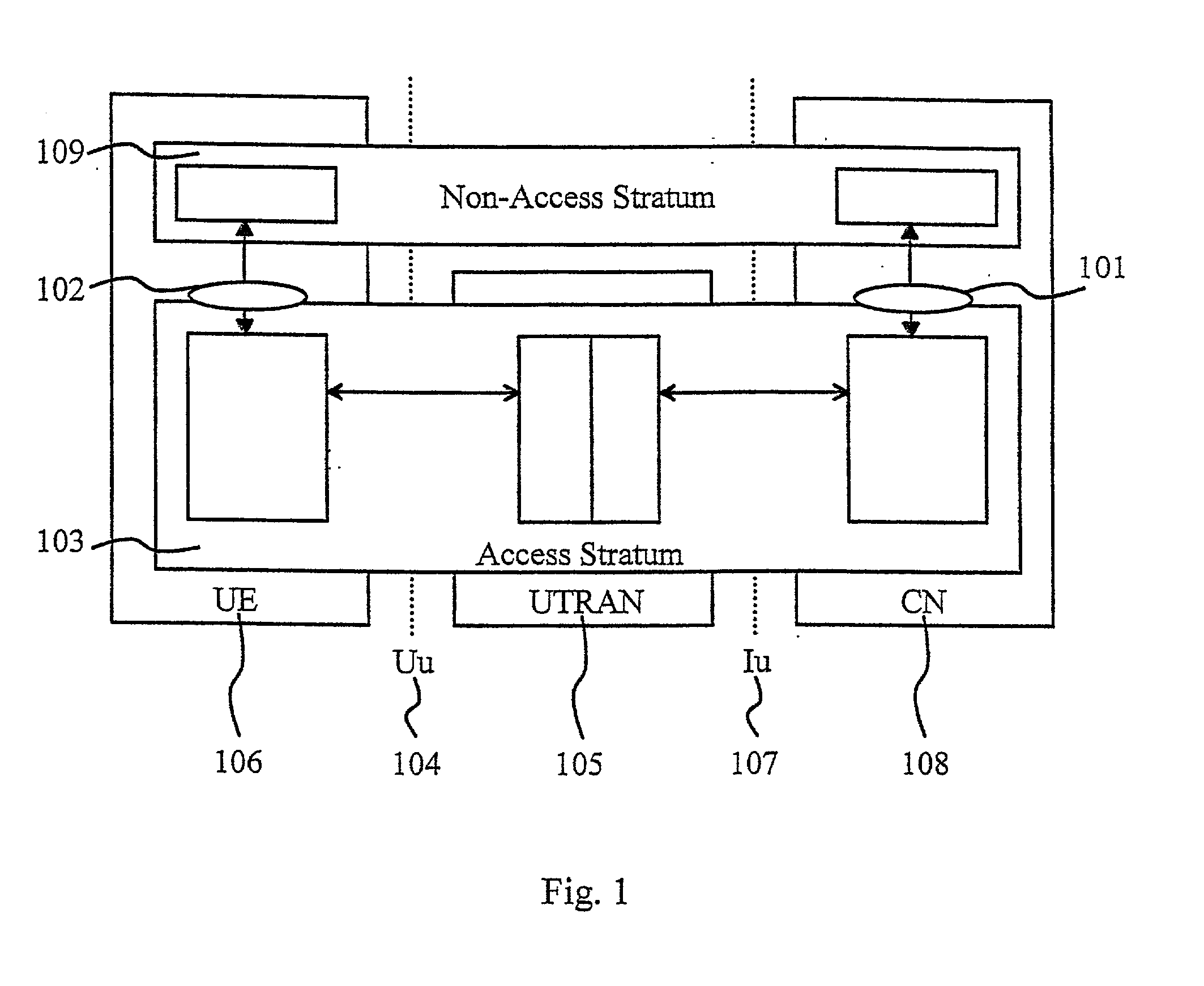
[0060] FIG. 1 shows a user plane in a UMTS, wherein the radio access bearer service is offered from SAP 101 to SAP 102 (or in the opposite direction) by the Access Stratum 103. The protocols on the Radio Interface 104, between a UTRAN 105 and a UE 106, and the interconnection point 107, between the UTRAN 105 and a Core Network 108 (CN), that are linked together to provide the Radio Access Bearer (RAB) service. The system of FIG. 1 can be used as a base for implementing the present invention. The present invention considers the data transfer from the UTRAN 105 to the User Equipment 106. FIG. 1 further shows a NonAccess Stratum 109 that offers higher layer signaling, which is not under consideration of the present invention.
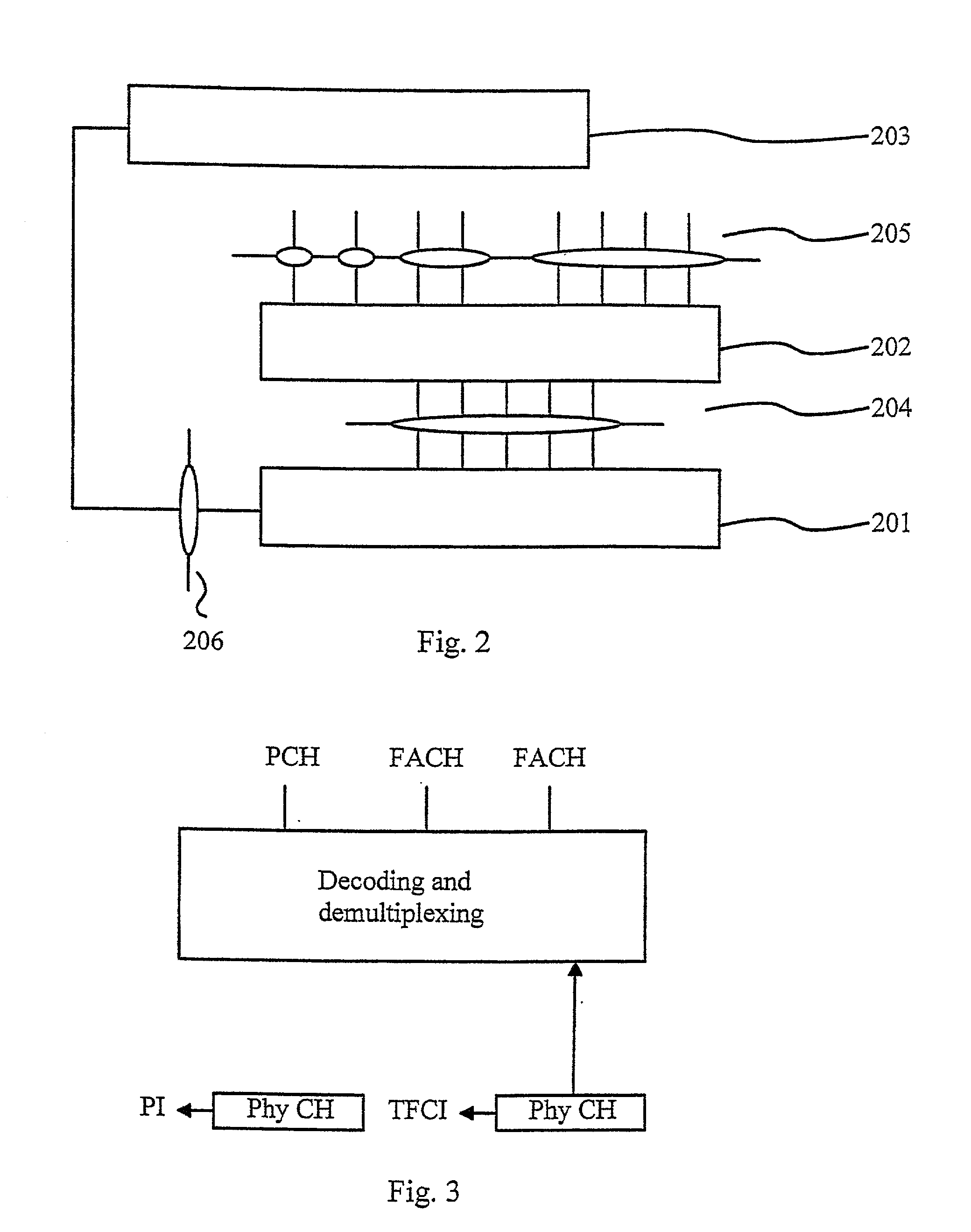
[0061] FIG. 2 shows a Radio Interface protocol architecture around a physical layer 201 (Layer 1). The physical layer 201 interfaces a Medium Access Control (MAC)-layer 202, which is a sub-layer of Layer 2, and the Radio Resource Control (RRC)-layer 203 of Layer 3....
PUM
 Abstract
Description
Claims
Application Information