Pressure plate assembly

a technology of pressure plate and assembly, which is applied in the direction of friction clutch, mechanical actuated clutch, clutch, etc., can solve the problem of incorrect representation of the true extent of wear which has occurred or been detected

Inactive Publication Date: 2002-04-18
ZF FRIEDRICHSHAFEN AG
View PDF0 Cites 3 Cited by
  • Summary
  • Abstract
  • Description
  • Claims
  • Application Information

AI Technical Summary

Problems solved by technology

In the case of the gripping element known from U.S. Pat. No. 6,123,180, however, the blocking element attacks the gripping element from the side, relative to the body section, upon the occurrence of wear, which means that the gripping element twists, with the result in turn that the gripping element, specifically the area of the gripping element which cooperates with the wear-comp

Method used


Image

  • Pressure plate assembly
  • Pressure plate assembly
  • Pressure plate assembly

Examples


Embodiment Construction

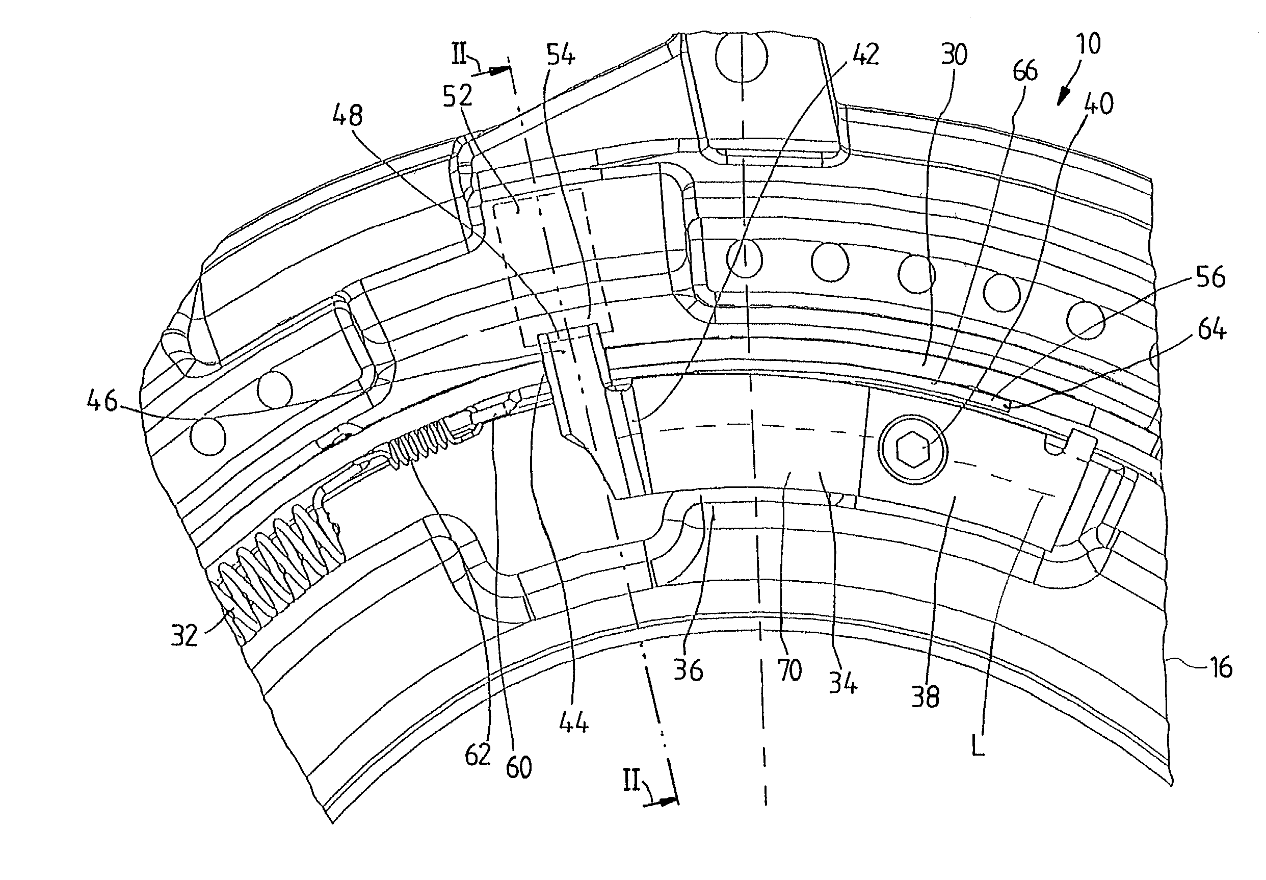
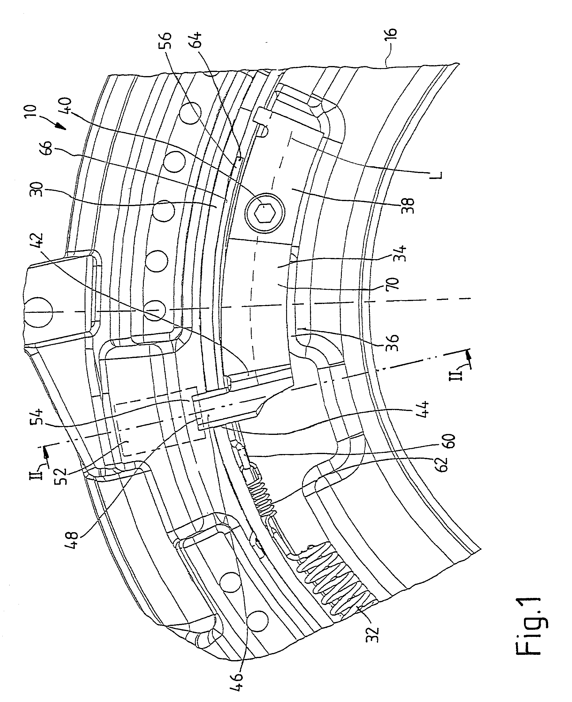
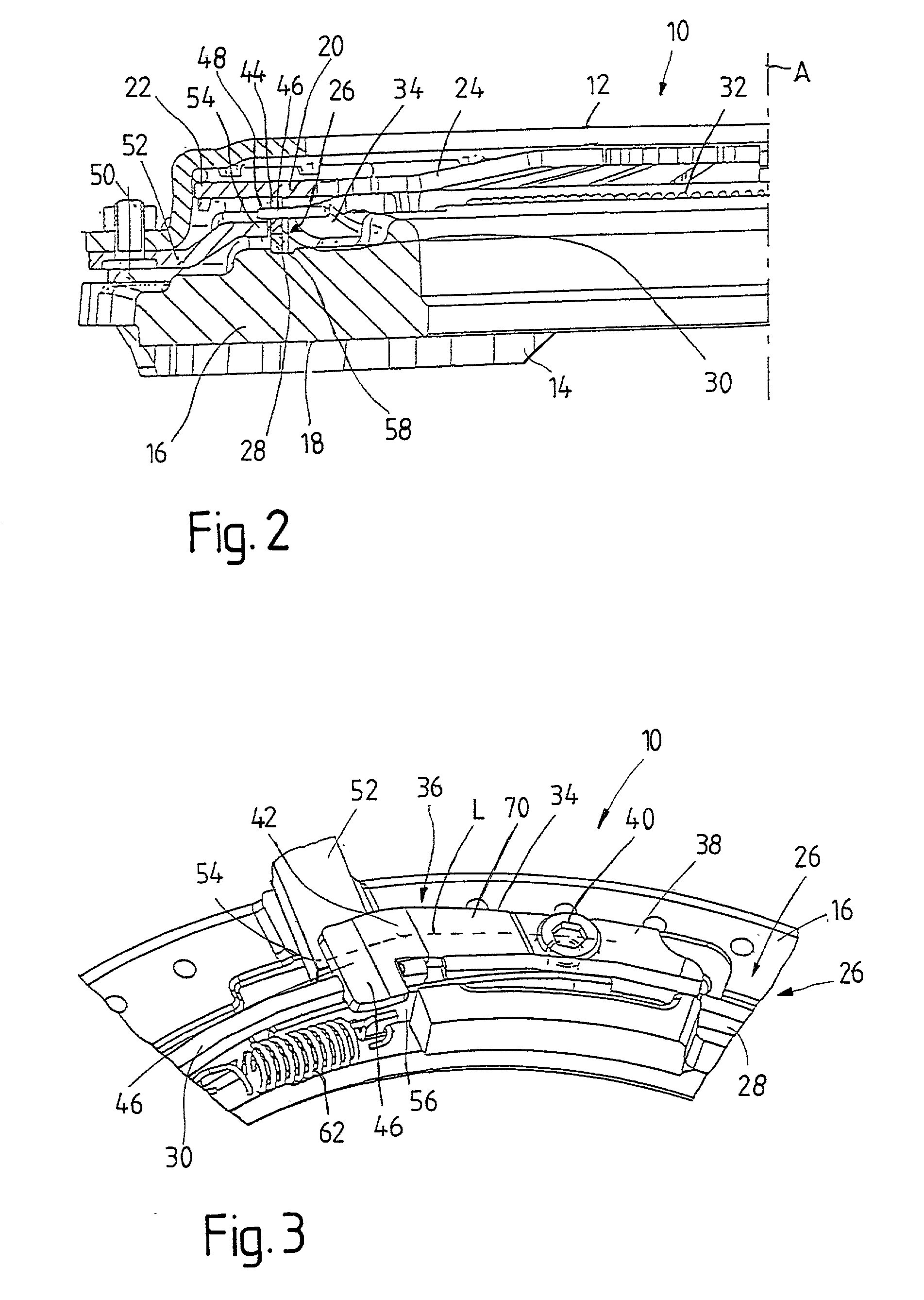
[0016] First, the design and function of a pressure plate assembly is described in general with reference to FIGS. 1 and 2. As will be described in conjunction with FIG. 3, the principles of the present invention can also be realized in this pressure plate assembly. Insofar as there are differences between the pressure plate designed according to the invention and the pressure plate assembly described in conjunction with FIGS. 1 and 2, a detailed discussion will be presented below.

[0017] The pressure plate assembly 10 shown in FIGS. 1 and 2 comprises a housing 12, which is designed to be attached to a centrifugal mass arrangement (not shown in the figures), such as a one-part flywheel or a possibly a multiple-mass flywheel. A pressure plate 16 is provided inside the housing 12; the friction surface 18 of this plate can be pressed against a clutch disk (not shown in the figures), and the clutch disk can thus be pressed against a corresponding friction surface of the centrifugal mass ...


PUM


Abstract

A pressure plate assembly for a friction clutch includes a housing; a pressure plate held in the housing with freedom to move in the same direction as that in which a rotational axis (A) extends; a stored-energy element; and a wear-compensating device acting in the path of force transmission between the stored-energy element and the pressure plate and/or between the stored-energy element and the housing arrangement, where the wear-compensating device has at least one adjusting element able to move in an adjusting direction to compensate for wear. A clearance-producing arrangement includes at least one gripping element, where the minimum of one gripping element has a body section, one end of which is attached to the assembly consisting of the pressure plate and the housing, between which assembly and the stored-energy element the wear-compensating device acts. The other end of the body section is designed with a blocking section projecting laterally from the body section to act on the wear-compensating device and to interact with a blocking element, which is able to shift position relative to at least part of the gripping element when wear occurs. It is in the area of its body section that the minimum of one gripping element interacts with the blocking element.

Description

[0001] 1. Field of the Invention[0002] The present invention pertains to a pressure plate assembly for a friction clutch comprising a housing arrangement; a pressure plate held in the housing arrangement with freedom to move axially; a stored-energy element; a wear-compensating device acting in the path of force transmission between the stored-energy element and the pressure plate and / or between the stored-energy element and the housing arrangement, where the wear-compensating device has at least one adjusting element able to move in an adjusting direction to compensate for wear; a clearance-producing device, comprising a gripping element, where the minimum of one gripping element has a body section, one end of which is fastened to the assembly consisting of the pressure plate and the housing, between which assembly and the stored-energy element the wear-compensating device acts, whereas the other end is designed with a blocking section projecting laterally from the body section to ...

Claims


Application Information

Patent Timeline
IPC IPC(8): F16D13/70F16D13/75
CPCF16D2013/706F16D13/757
Inventor GORZITZKE, KLAUSHERTERICH, WINFRIEDKNAUER, WOLFGANGLINDNER, WALTERLINK, ACHIMROLL, GERHARDWEIDINGER, REINHOLD
Owner ZF FRIEDRICHSHAFEN AG
Why Eureka
Try Eureka