
Handover method in wireless telecommunication system supporting USTS

a wireless telecommunication system and handover technology, applied in multiplex communication, wireless commuication services, synchronization arrangement, etc., can solve the problems of limited capacity of reverse channels, interference between reverse channels becomes increased, and reverse channels cannot be synchronized

Inactive Publication Date: 2002-04-18
SK TELECOM CO LTD
View PDF5 Cites 208 Cited by
  • Summary
  • Abstract
  • Description
  • Claims
  • Application Information

AI Technical Summary

Benefits of technology

[0020] Therefore, it is an object of the present invention to provide a handover method which provides a mobility to a mobile station based a mode conversion between an uplink synchronous transmission scheme (USTS) mode and a non-USTS mode in a CDMA telecommunication system supporting the USTS.

Problems solved by technology

However, since the timing information is not used in the reverse channel, the reverse channels cannot be synchronized.
As the number of the reverse channels is increased, the interference between the reverse channels becomes increased.
Therefore, a capacity of the reverse channel is limited.
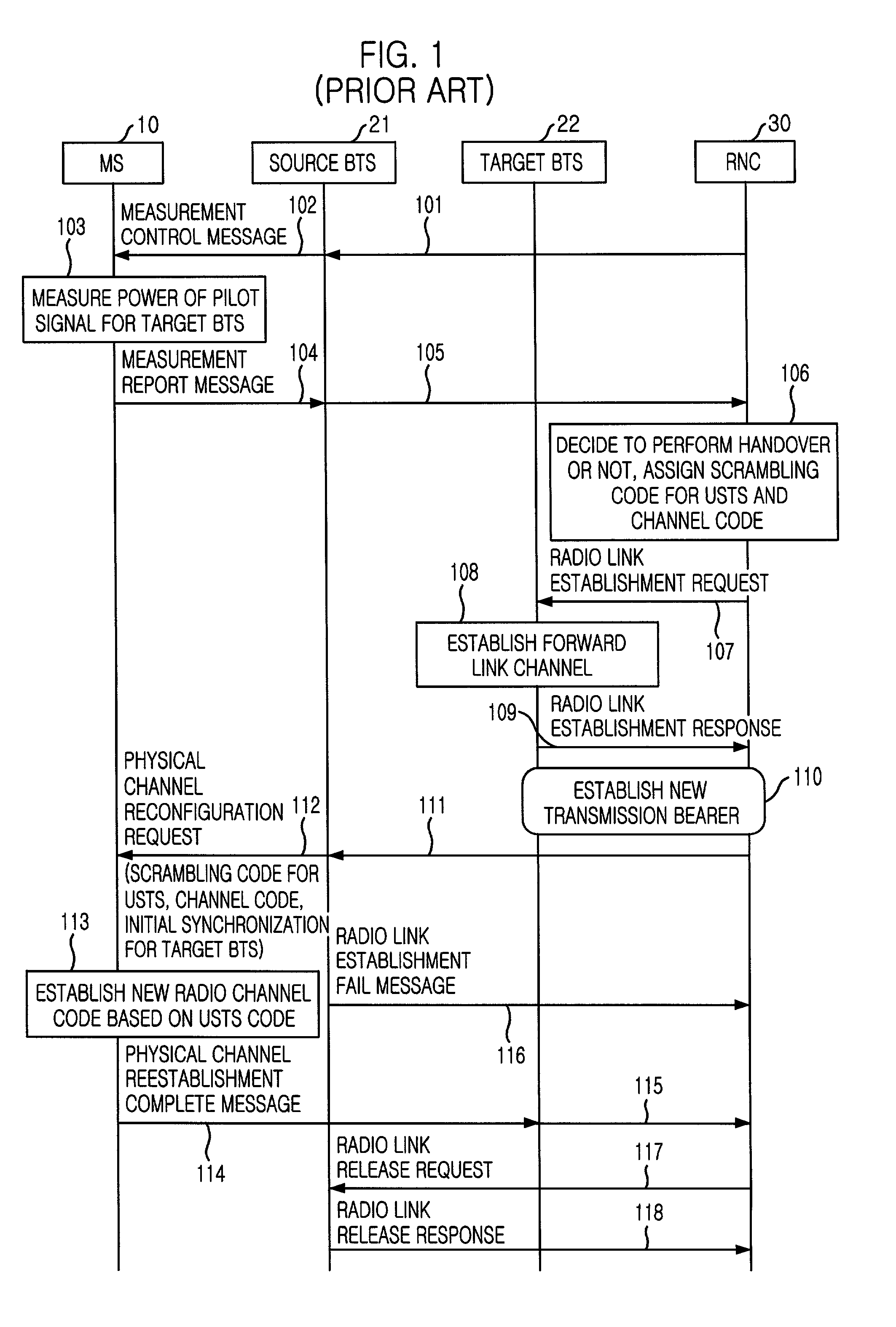
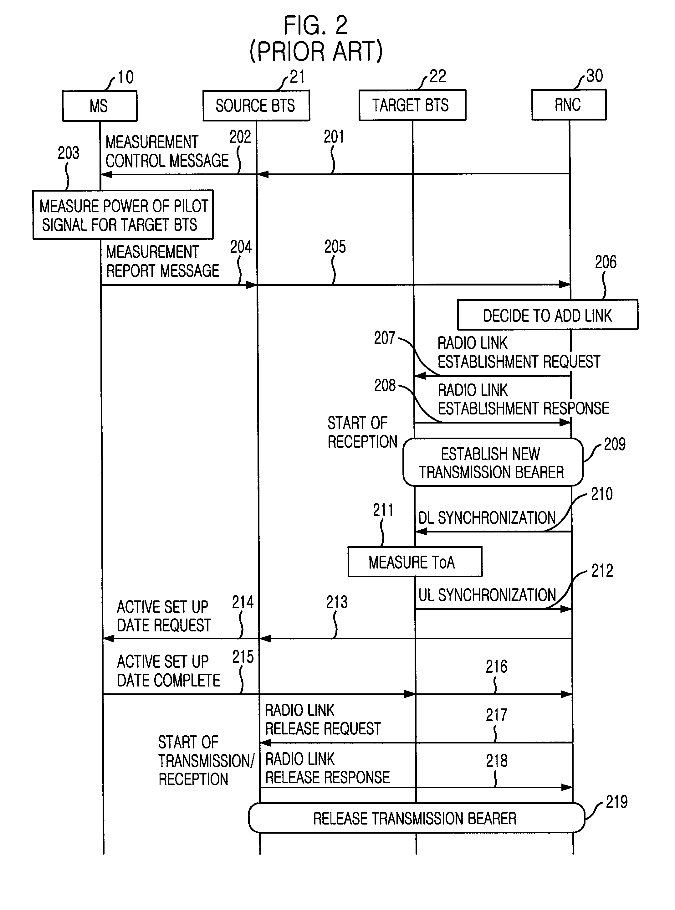
In the system using the USTS, the reverse channels within a cell are synchronized, and each of the reverse channels is identified by the orthogonal code based on the synchronization between the MS and the BTS, thereby causing a serious problem in that a soft handover method using a diversity is difficult to be performed.
Therefore, handover methods in the system using the USTS, which are required for providing a mobility of the MS, are not yet provided.
However, since it is difficult to obtain the accurate timing synchronization when performing the handover, the timing synchronization should be compensated by timing tracking.
Therefore, there is a problem in that the mode conversion to USTS mode is difficult to be performed for a while after the handover.
Therefore, if multiple mobile stations try to perform the soft handover simultaneously, the target BTS recognizes all of signals from the multiple mobile stations as the signals from one mobile station, such that the signals cannot be decoded.

Method used


Image

  • Handover method in wireless telecommunication system supporting USTS
  • Handover method in wireless telecommunication system supporting USTS
  • Handover method in wireless telecommunication system supporting USTS

Examples


Embodiment Construction

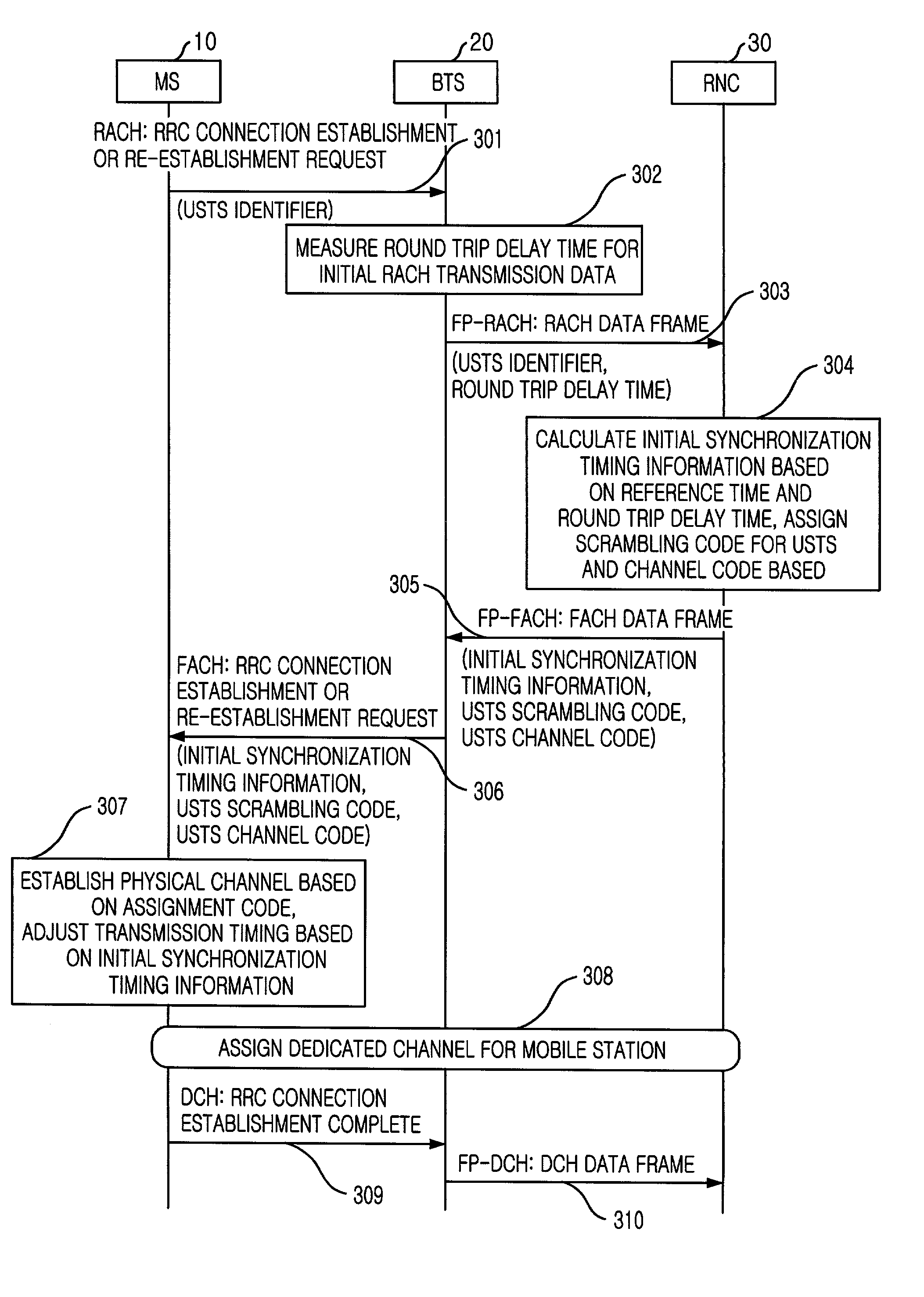
[0036] First, the uplink synchronous transmission scheme (USTS) technology will be described in more detail.

[0037] In the system supporting the USTS, by controlling the transmission time of the data frame in the reverse channel, i.e., the transmission time of the data frame from the MS within its cell, the BTS makes the reverse signals using the orthogonal code to be simultaneously arrived at the BTS, and therefore characteristics of the orthogonal code can be maximized, to thereby considerably increase the transmission capacity of the cell.

[0038] In other words, the USTS increases efficiency of the reverse channel as much as that of the forward channel. For the USTS, a scrambling code and an orthogonal channel code are used for identifying a cell and a channel of a mobile station. The BTS has a reference time for its cell, and the MS is not affected on the reference time of the BTS before an initial access to the BTS.

[0039] If the MS tries an access to the BTS through a random acce...


PUM


Abstract

A handover method in wireless telecommunication system supporting USTS is disclosed. The method for performing a handover of a mobile station in an asynchronous wireless telecommunication system supporting an uplink synchronous transmission scheme (USTS) mode, includes the steps of: a) performing a mode conversion of the mobile station from the USTS mode to a non-USTS mode based on a first signal measurement result from the mobile station; and b) performing a handover for the mobile station. In another embodiment of the present invention, the method further includes the step of: c) performing a mode conversion from the non-USTS mode to the USTS mode based on a second signal measurement result from the mobile station.

Description

[0001] The present invention relates to a handover method in a wireless telecommunication system; and, more particularly, to a handover method in a code division multiple access (CDMA) wireless telecommunication system supporting an uplink synchronous transmission scheme (USTS).DESCRIPTION OF THE PRIOR ART[0002] A traffic channel between a base station (BTS, which is also referred to as "a node B") and a mobile station (MS, which is also referred to as "a user equipment") in a conventional code division multiple access (CDMA) system includes a forward channel (which is also referred to as "a downlink channel") and a reverse channel (which is also referred to as "an uplink channel"). At this time, multiple forward channels between the base station and multiple mobile stations located within a coverage (cell) of one base station are synchronized with each other based on timing information. Therefore, when demodulating signals, interference between the forward channels can be considera...

Claims


Application Information

Patent Timeline
Patent Type & Authority Applications(United States)
IPC IPC(8): H04J13/00H04J13/18H04L7/00H04W36/18H04W36/30H04W36/36H04W56/00H04W72/54H04W74/02
CPCH04W36/18H04W72/085H04W36/30H04W72/542H04W36/302
Inventor PARK, SEONG-SOOCHO, JIN-HOLEE, IN-HONGLEE, JIN-ICK
Owner SK TELECOM CO LTD
Learn More