
Composite power cable

a technology of composite power cables and power cables, which is applied in the direction of power cables, cables, insulated conductors, etc., can solve the problems of long manufacturing time, complex process of composite power cables, and long manufacturing tim

Inactive Publication Date: 2002-05-09
FURUKAWA ELECTRIC CO LTD
View PDF0 Cites 26 Cited by
  • Summary
  • Abstract
  • Description
  • Claims
  • Application Information

AI Technical Summary

Problems solved by technology

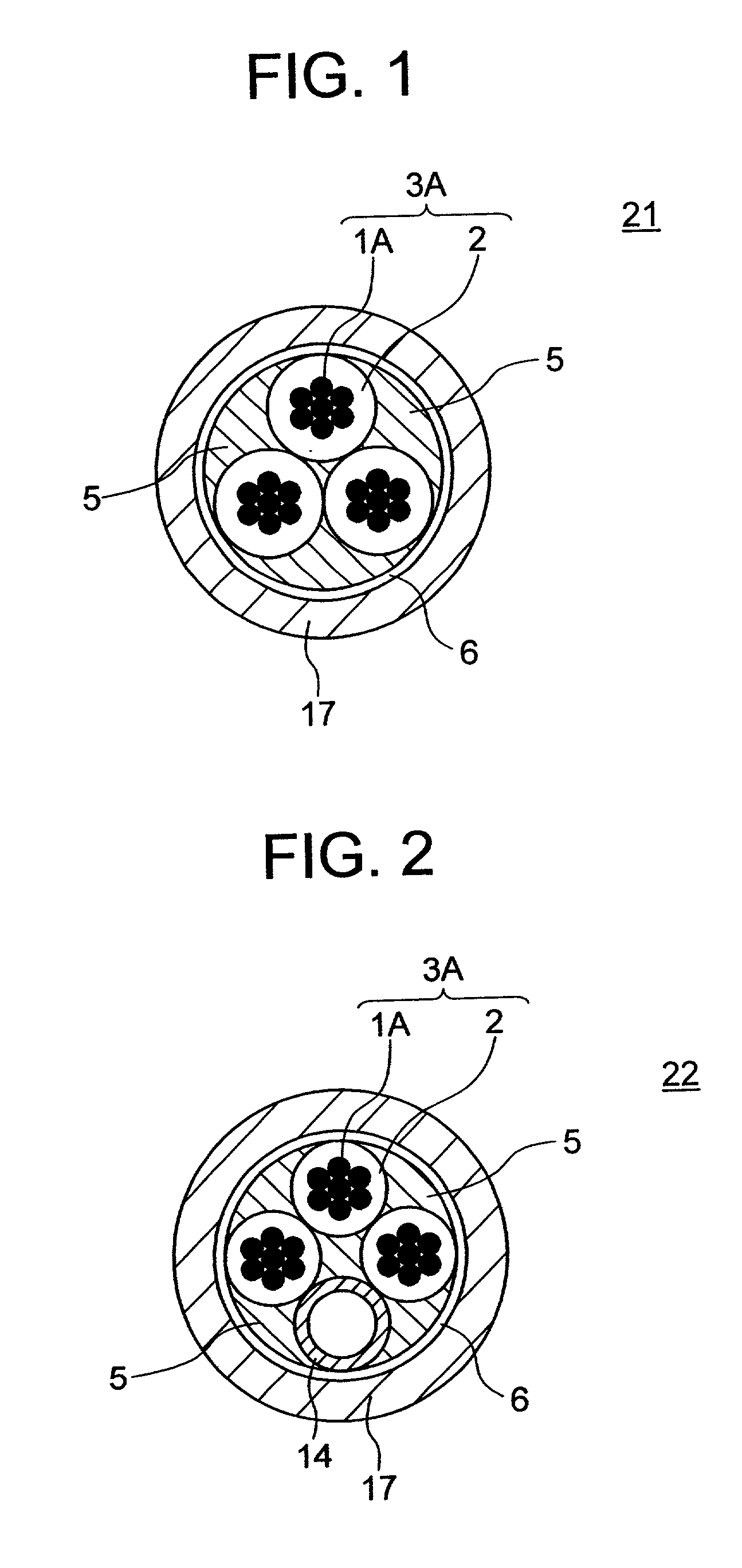
Further, the process of production includes a step of twisting together the insulated conductors 3A and the pipe 14, so the process of production of the composite power cable becomes complex and the manufacturing time also becomes long.
Especially, since the members are twisted together by relatively short pitch in the above way since consideration is given to the bending etc. when laying the composite power cable, the problems are encountered that the manufacture is complex, the manufacturing time becomes long, and as a result the price of the composite power cable becomes more expensive.
Thus, the problem of the high price of the composite power cable becomes a serious obstacle especially when laying a large number of composite power cables to general homes.
In addition, at the portion where the composite power cable 22 is laid bent, the problem is encountered that the efficiency of insertion of the optical fiber unit 12 into the pipe 14 becomes low, the insertion of the optical fiber unit 12 becomes difficult, and the work efficiency becomes lower.
In addition, it was very difficult to insert the optical fiber unit 12 into the pipe 14 of the composite power cable 22 at the portion where the composite power cable 22 was laid in a bent state.

Method used


Image

  • Composite power cable
  • Composite power cable
  • Composite power cable

Examples


Embodiment Construction

[0073] Next, an explanation will be made of an example of the present invention based on the above embodiments.

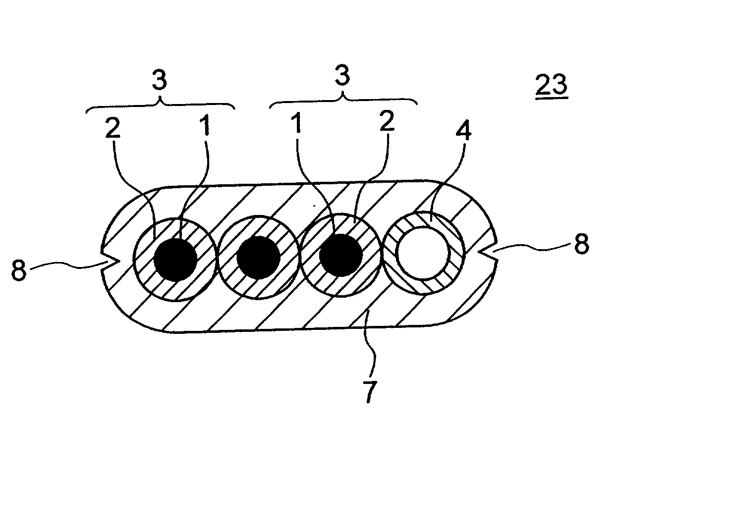
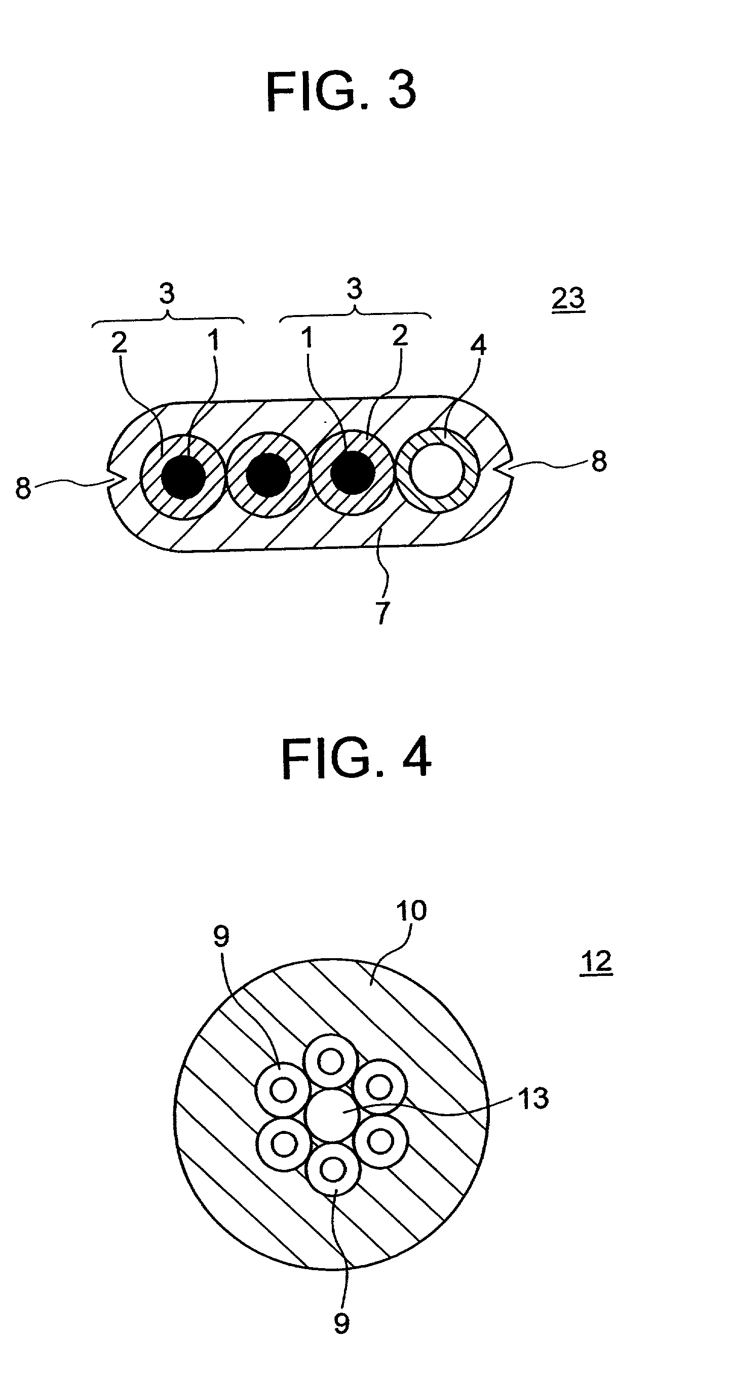
[0074] As an example of the present invention, a composite power cable 23 of the structure illustrated in FIG. 3 having the insulated conductors 3 and the pipe 4 was prepared, then the optical fiber unit 12 in FIG. 4 was inserted into the pipe 4. Next, the mechanical properties and temperature characteristics of the composite power cable 23 with the optical fiber unit 12 inserted in the pipe 4 were evaluated. Further, the insertability of the optical fiber unit 12 in the composite power cable of the present invention was evaluated simulating the actual state of laying the cable. Details will be described below.

[0075] (1) Manufacture of Insulated Conductors 3

[0076] First, three insulated conductors 3, each comprised of a power conductor 1 of JISC3102 electrical use soft copper wire and 2 mm diameter covered by an insulator 2 made of Poly vinyl chloride compound conforming wi...


PUM


Abstract

To provide a low price, easy to produce, and easy to lay composite power cable, comprised of a pipe (4) able to receive a communication cable such as an optical fiber and an insulated conductor (3). A plurality of insulated conductors (3) each comprised of a conductor (1) and an insulator (2) and at least one pipe (4) are arranged in a line in a direction perpendicular to the longitudinal direction and are covered all together by a covering (7) when arranged in a straight line in the longitudinal direction. Preferably, an outer diameter of the pipe is made not more than 1.2 times the maximum value of an outer diameter of an insulated conductor arranged adjacently. More preferably, grooves are provided in the longitudinal direction of the cable in the two side surfaces in a width direction of the flat-shaped covering.

Description

[0001] The present invention relates to a composite power cable comprised of a power cable used for indoor wiring etc. combined with an optical fiber, a communication cable, or other communication use line-shaped member.PRIOR ART[0002] The development of the Internet and other communication networks and the increase in the volume of communication have been accompanied with accelerated use of optical communications using optical fibers. Optical fibers are being laid not only to companies of course, but also general homes. The laying of communication lines using optical fibers has been accompanied by requests for laying optical fibers indoors so as to enable connection of the optical fibers to personal computers and other terminal equipment installed inside the general home.[0003] At the present time, power cables and communications cables for telephones etc. are being laid indoors separately from and independently of each other. Therefore, to avoid complication of laying of cables, i...

Claims


Application Information

Patent Timeline
IPC IPC(8): G02B6/44H01B7/00H01B7/08H01B7/38H01B9/00H01B11/22
CPCG02B6/4416G02B6/4459H01B7/0072H01B9/005H01B7/38H01B9/003H01B7/0823
Inventor TAKEDA, YOSHITERUKOBAYASHI, ICHIRO
Owner FURUKAWA ELECTRIC CO LTD
Learn More