Receiver with feedback filter, and eye monitor for the feedback filter

a technology of feedback filter and eye monitor, which is applied in the direction of instruments, electrical appliances, optics, etc., can solve the problems of large phase fluctuation, main limiting criterion of signal dispersion of optical signals, and remaining problems

Inactive Publication Date: 2002-05-23
ALCATEL LUCENT SAS
View PDF5 Cites 81 Cited by
  • Summary
  • Abstract
  • Description
  • Claims
  • Application Information

AI Technical Summary

Problems solved by technology

Apart from attenuation, signal dispersion of the optical signals is the main limiting criterion which influences transmission links and bit rates in fibre-optic systems.
However, in the case of very large distortions such as occur in the case of a large PDM, for example, the following problem occurs: the signal clock pulse regenerated with conventional clock pulse circuits has a large phase fluctuation, the

Method used


Image

  • Receiver with feedback filter, and eye monitor for the feedback filter
  • Receiver with feedback filter, and eye monitor for the feedback filter
  • Receiver with feedback filter, and eye monitor for the feedback filter

Examples


Embodiment Construction

[0010] The invention concerns an optical receiver with an electronic filter, the threshold values of which are set through eye monitors. The invention additionally concerns a high-speed eye monitor which permits direct measurement of the quality of the transmission link, including in the case of high bit rates.

[0011] Embodiment examples of the invention are represented in the drawing and explained more fully in the following description.

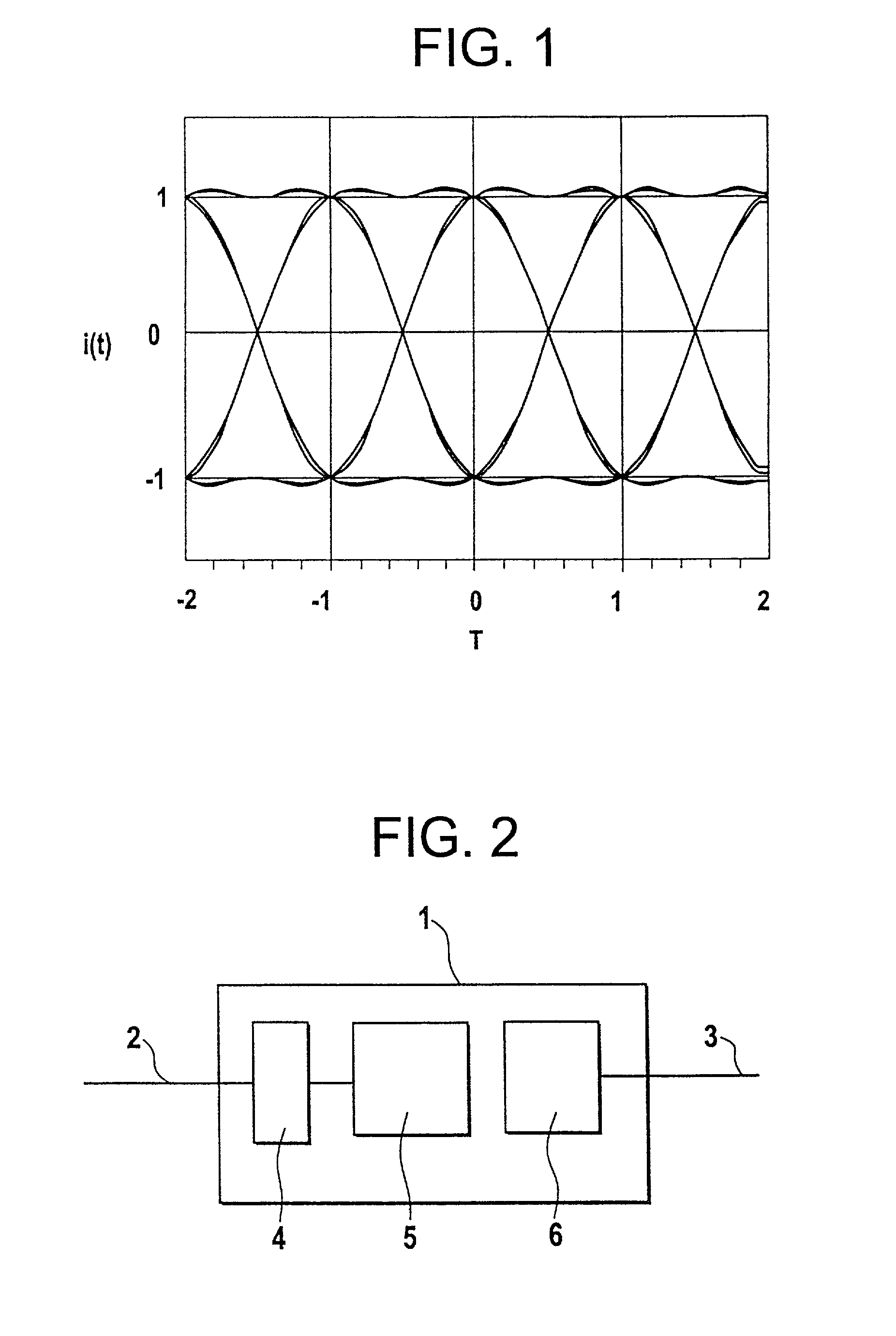
[0012] FIG. 1 shows an eye diagram,

[0013] FIG. 2 shows, in schematic form, a receiver with an eye monitor,

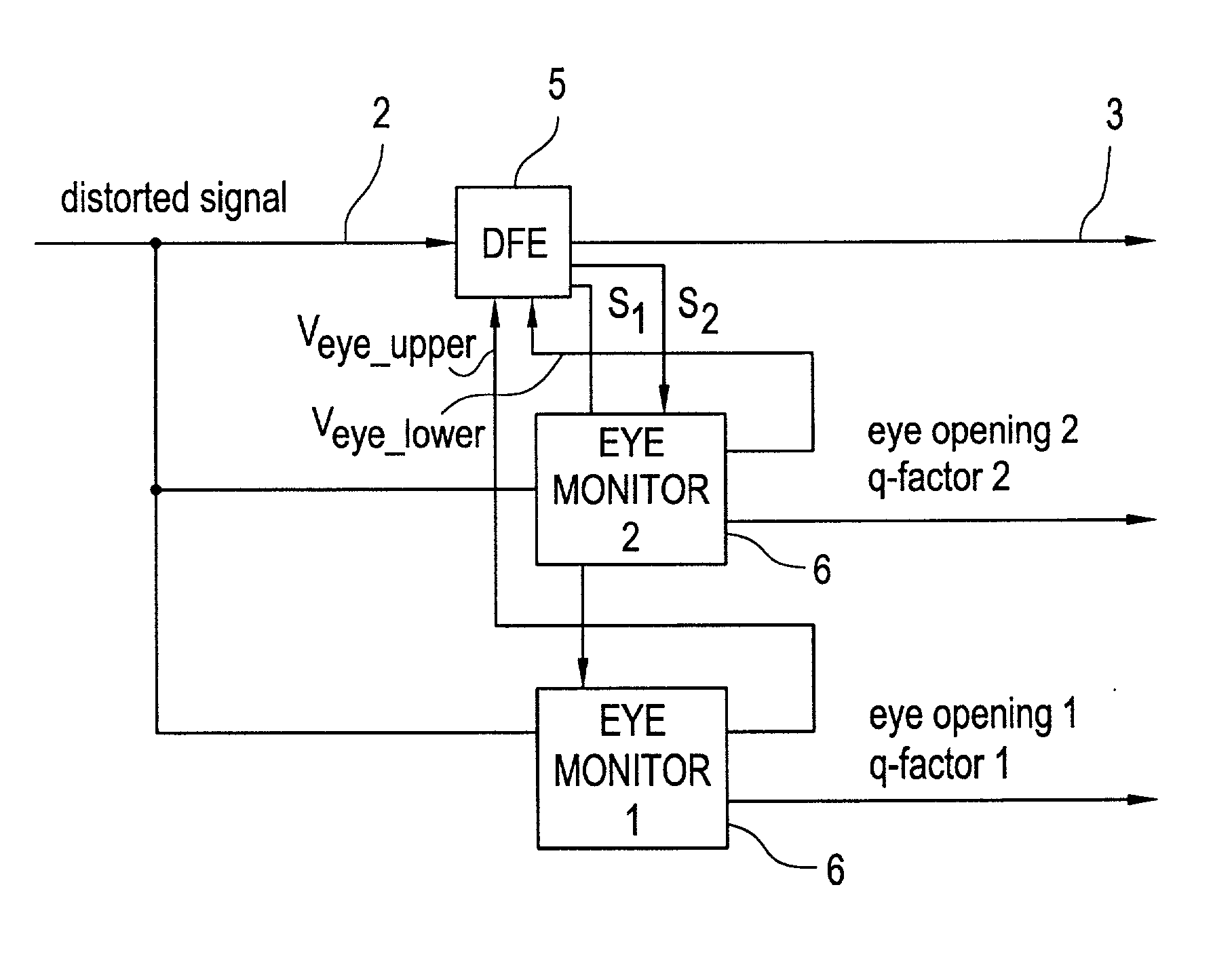
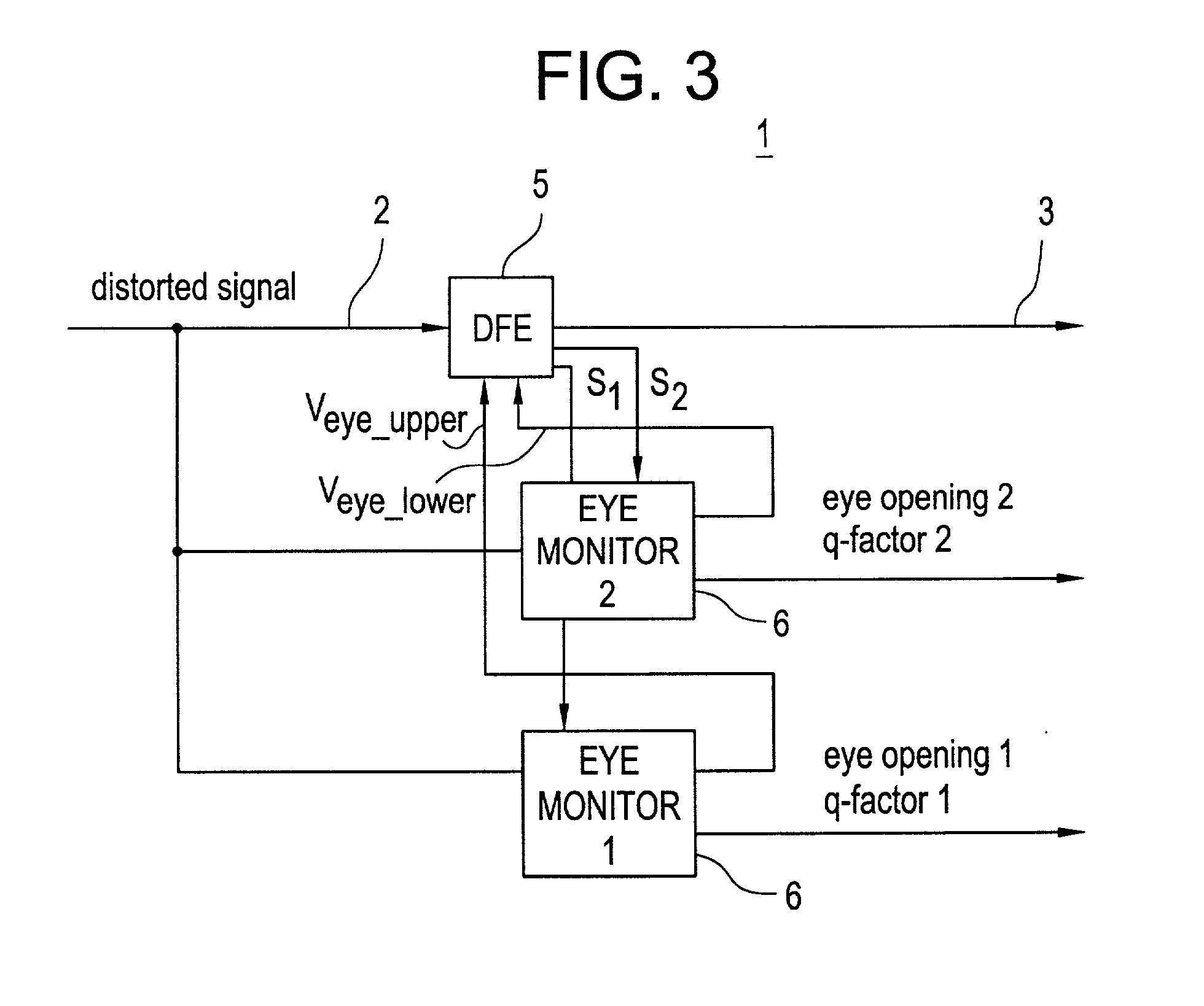
[0014] FIG. 3 shows a receiver with a DFE and eye monitors,

[0015] FIG. 4 shows an embodiment of a high-speed eye monitor,

[0016] FIG. 5 shows a result of the measurement of the eye height, and

[0017] FIG. 6 shows the influence of the small signal on the measurement of the eye height.

[0018] A receiver 1 for optical signals is shown schematically in FIG. 2. The receiver 1 is connected to an optical transmission link 2. In the receiver 1 there is an o...


PUM


Abstract

An optical receiver with an electronic filter is described, the parameters of the filter being set by means of high-speed eye monitors. Also described is a high-speed eye monitor with threshold-value decision elements which are set close to the vertices of the eye of an eye diagram, the eye monitor being optimized through connection of a pseudo-error generator and comparison with setpoint values and outputting the eye opening and the Q-factor.

Description

PRIOR ART[0001] The invention is based on the priority application DE10052279.3. The invention is based on a receiver with a feedback filter and on an eye monitor for the feedback filter. The invention is furthermore based on a method for determining a digitally transmitted optical signal and on a method for rapidly measuring the eye opening and the Q-factor of a data signal.[0002] Apart from attenuation, signal dispersion of the optical signals is the main limiting criterion which influences transmission links and bit rates in fibre-optic systems. The effect of the dispersion and its limitations can be compensated by appropriate signal processing of the optical signal and of the recovered electrical signal. In practical application, the signal processing must be adaptive, since the dispersion effects of the fibres vary with time. The dispersion effects, caused, for example, by polarization mode dispersion, result in overlapping of signal components of different polarization. Due to...

Claims


Application Information

Patent Timeline
IPC IPC(8): H04B10/00H04B10/02H04B10/079H04B10/08
CPCH04B10/0799H04B10/07953
Inventor BUCHALI, FRED
Owner ALCATEL LUCENT SAS
Why Eureka
Try Eureka