
Probe style radiometer

a radiometer and probe-type technology, applied in the direction of photometry using electric radiation detectors, optical radiation measurement, instruments, etc., can solve the problems of high cost, high cost, and high cost of quartz rods

Inactive Publication Date: 2002-05-30
ELECTRONICS INSTR & TECH INC
View PDF0 Cites 9 Cited by
  • Summary
  • Abstract
  • Description
  • Claims
  • Application Information

AI Technical Summary

Benefits of technology

[0011] It is another object of the present invention to provide a probe-style radiometer which is constructed to prevent a user from experiencing an electrical shock.
[0026] The probe design of the present invention avoids these hazards. Although the probe preferably has a metallic core, it is clad in a very hard, durable, electrically non-conductive coating which is able to withstand, for example, up to 5 KV and can operate in temperatures of up to 1200.degree. F. This coating may, for example, be a ceramic-based material. The probe itself is also electrically isolated form the portion of the instrument in physical contact with the operator. The isolation is obtained by using an electrically non-conductive block that mechanically connects the probe to the instrument body.

Problems solved by technology

This design has several problems.
The first problem is cost and performance.
This drives the cost of the quartz rod upward, as the better the transmission the higher the cost.
Moreover, a quartz rod may break if struck with a sharp blow.
Other probe designs which use quartz fibers are not as susceptible to sharp blows but instead are very susceptible to changes in light output associated with bending of the fibers.
Also, the fibers tend to be quite expensive when made of fused silica.
A second problem is related to the metallic surface of the sheath or cladding which encases the quartz rod or fibers.
This metallic cladding presents serious electrical shock and arcing hazards when the probe is inserted into an operating UV environment.
Contact by the operator with these sources is very hazardous.
Further, shorting these power sources through a metal conductor to a machine body or other ground potential presents a hazardous arcing potential.
A third problem relates to the cross-sectional shape of the probe.
This is undesirable because rotation of the tip of the probe around its longitudinal axis will causes changes in the measured reading.
The round cross-section thus makes it difficult for a user to precisely position the probe for proper and consistent measurement.

Method used


Image

  • Probe style radiometer
  • Probe style radiometer
  • Probe style radiometer

Examples


Embodiment Construction

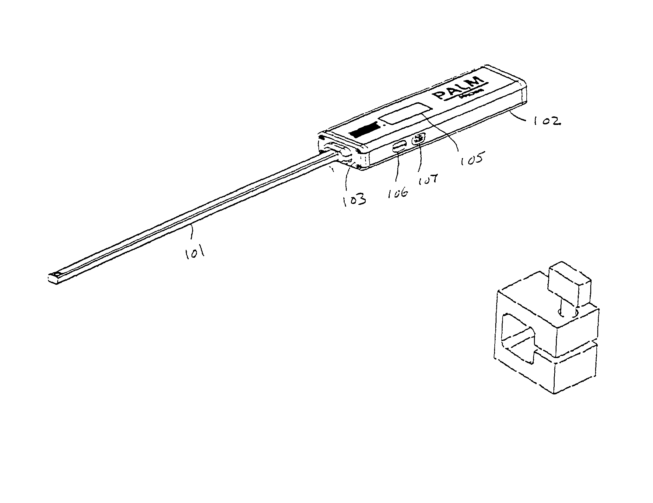
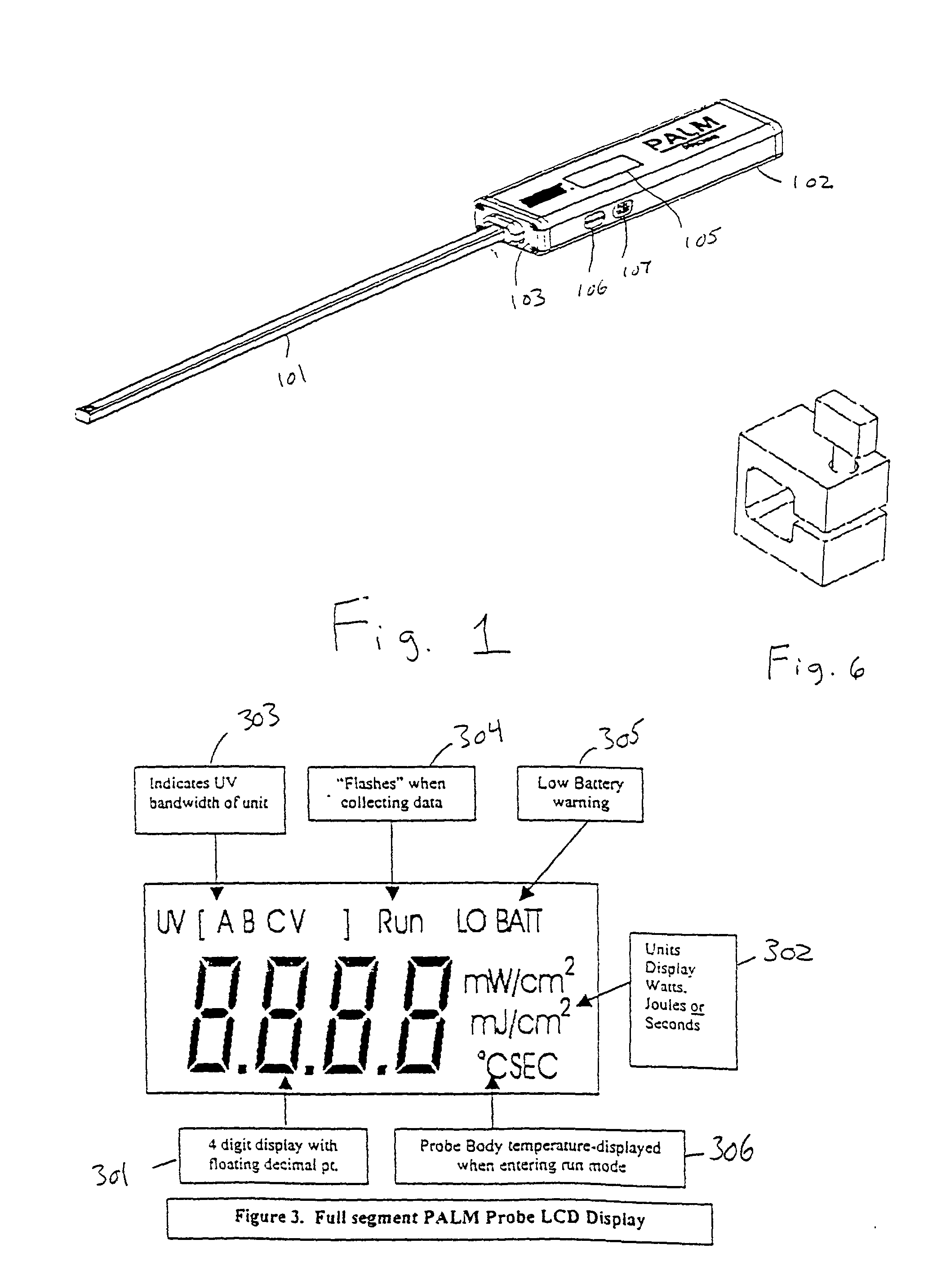
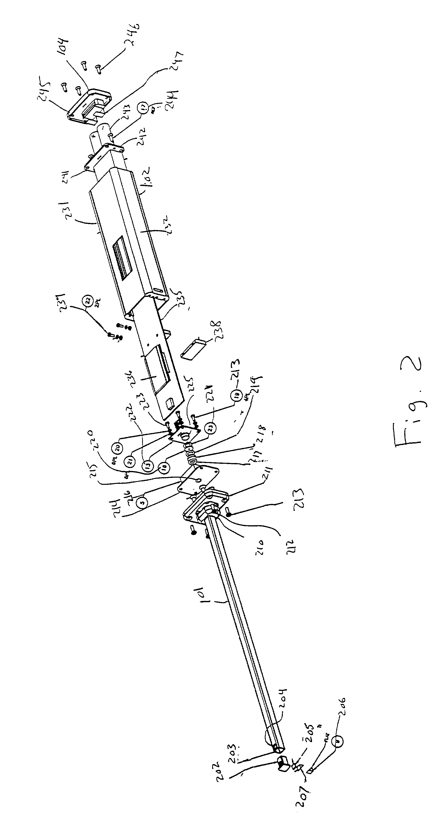
[0034] Referring now to the drawings and more particularly to FIG. 1, a probe style radiometer according to one embodiment of the invention includes a probe 101 and an instrument body 102. The probe may be a hollow rod made of a rigid material which is either conductive or nonconductive. Preferably, probe 101 is a hollow metal rod having a substantially rectangular cross-section. Alternatively, the rod may be filled with a light-guiding medium such as glass or optical fiber. For example, if desired, probe 101 may use as its internal light-guiding medium metal clad glass, quartz, or optical fiber. Further, for enhanced protection, the glass, quartz, or fiber may contain an insulating coating.

[0035] Body 102 contains optical and electronic circuitry for detecting and processing the ultaviolet radiation collected by the probe. The body also serves as a handle. Preferably, the body has physical dimensions which comfortably fit a user's hand. This may be achieved by constructing the body...


PUM


Abstract

A probe style radiometer includes a generally rectangular cross-sectional body and a probe having a square cross-section. The probe is preferably a hollow rod having a tip equipped with a UV-collecting aperture and a mirror. The mirror reflects UV light entering the aperture down the length of the rod to a detector in the body. A processor in the body then computes the amount of UV radiation based on signals from the detector. The amount may then be provided on a display integrated into the body. A ground quartz or glass window may be provided at the tip to seal the rod from exterior contamination and to diffuse the incoming UV radiation in a manner that will give the probe a near-cosine angular response. Filters within the radiometer body then filter this diffused radiation to the spectral region of interest. Preferably, the radiometer is battery powered and includes switches on the body to allow a user to control the mode of operation. To prevent electrical shock, the metal rod of the probe may contain an electrically non-conductive outer coating.

Description

[0001] 1. Field of the Invention[0002] The present invention generally relates to probe style radiometers, and more particularly to a high dynamic range, cost effective and safe probe radiometer for measuring ultraviolet (UV) radiation in a production environment.[0003] 2. Background Description[0004] Use of ultraviolet light in the printing and coatings industry has grown rapidly over the past several years. Special ink and coating formulations will polymerize, or "cure," with exposure to light in the ultraviolet (UV) region of the spectrum. Measurement of the amount and intensity of UV exposure a product receives during the manufacturing process is paramount in establishing and maintaining process control. UV radiometers are used to measure the amount of UV light to which a product is exposed. There is much variation in the configuration of UV curing production lines. As a result, many different types of radiometers are used. The different configurations are driven by both physica...

Claims


Application Information

Patent Timeline
Patent Type & Authority Applications(United States)
IPC IPC(8): G01J1/42
CPCG01J1/429
Inventor MAY, JOE T.CAIN, MICHAEL SCOTTRAYMONT, JAMES M.ROGERS, CHRISTOPHER S.SHORTER, CHRISTOPHER S.
Owner ELECTRONICS INSTR & TECH INC
Learn More